Author:
Helen Garcia
Date Of Creation:
16 April 2021
Update Date:
26 June 2024

Content
Alternating current (AC) is used to transmit electricity over long distances, as well as to power high-power appliances and lighting. The properties of alternating current allow large amounts of energy to be transmitted over long distances, for example for heating or lighting. Low-power devices and devices must be powered with a constant current of the required voltage. Since AC power flows in a typical wall outlet in most homes, it must be converted to DC for many applications. In this manual, you will learn about the basic principles of designing and assembling an electric current rectifier.
Steps
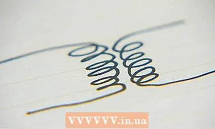
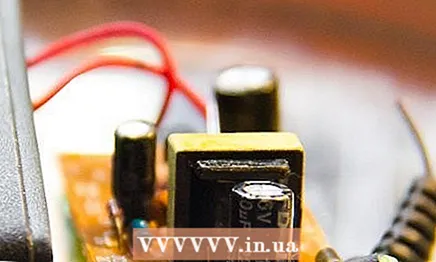 1 Select a transformer. The transformer consists of two coils (windings) inductively connected to each other. One of the coils is called the primary winding. The primary winding receives current from a voltage source (socket). The current from the secondary winding feeds the rectifier. All the necessary parts (including the transformer) can be purchased at the radio parts store.
 - Determine the number of turns on the windings. An alternating current with a voltage of 220 V flows in the outlet. If you rectify this current without a transformer, its voltage will be too high to power equipment and devices. The secondary voltage depends on the number of turns.
- Select a transformer such that the output voltage matches that required to power the device.
 2 Solder the ends of the primary winding of the transformer to a wire with a plug to connect to a voltage source. Transformers do not require polarity.
 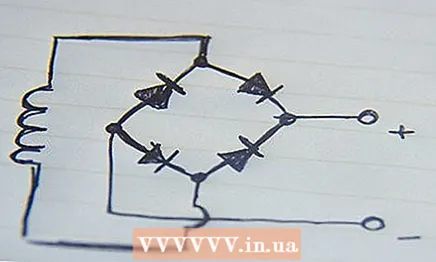 3 Solder the ends of the secondary winding to the diode bridge. If you are using a single-frame bridge, the ends of the secondary are connected to the unmarked terminals "+" or "-".
 - You can assemble the diode bridge yourself. The diode bridge consists of four diodes. The diode electrodes (anodes and cathodes) must be connected in a loop. Connect the negative terminal (cathode) of the first diode to the cathode of the second. Connect the positive terminal of the second diode (anode) to the cathode of the third diode. Solder the anode of the third diode to the anode of the fourth. Solder the cathode of the fourth diode to the anode of the first.
- Solder the secondary leads to the diode bridge. Solder one end to the cathode of the third diode and the other to the cathode of the fourth. Then at the junction of the cathodes of the first and second diodes there will be a positive pole, and at the junction of the third and fourth diodes there will be a negative pole.
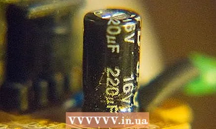 4 Add a smoothing capacitor to the circuit. A polarized capacitor is connected in parallel between the terminals of the diode bridge. Observe the polarity, the positive lead of the capacitor is connected to the positive lead of the bridge, and the negative lead to the negative. The capacitance of the capacitor is calculated by the formula C = (3200 * I) / U * 0.01 where C is the required capacitance (in microfarads), I is the maximum load current (in amperes), U is the required voltage (in volts). Remember that the filter capacitor increases the output voltage by 1.41 times, and the voltage after the diode bridge drops by 1.5-2 volts, so select the transformer accordingly.
 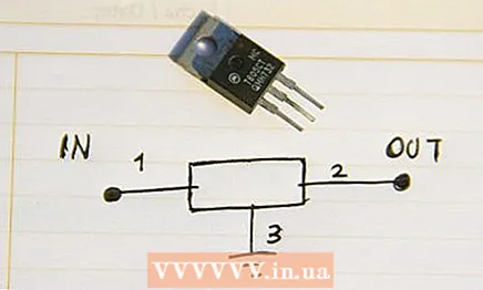 5 Add stabilizer. Select an appropriate voltage regulator. Domestic stabilizers ("rolls") and foreign analogs, as a rule, have three outputs: input, common and output. A voltage regulator completes the rectifier circuit.
 - You can check the connection diagram and pinout of the stabilizers in the manufacturer's documentation. Perhaps the documentation and the typical wiring diagram will indicate the need for a second noise suppression capacitor. Purchase and include in the circuit the capacitor specified in the stabilizer documentation.
What do you need
- Transformer
- Diode bridge
- Diodes
- Electrolytic capacitors
- Stabilizer
- Passive stabilizer strapping (see stabilizer documentation)


