Author:
Mark Sanchez
Date Of Creation:
1 January 2021
Update Date:
1 July 2024

Content
Transformers are stationary electromechanical devices, the work of which is based on the fact that any alternating electric field creates a magnetic field, and any magnetic field generates an electric one. This allows two circuits that are electrically isolated from each other to interact. The current in the first circuit creates a magnetic field around it, which, acting on the second circuit and transferring its energy to it, creates a current in it. This article will show you how to test a transformer.
Steps
 1 Check the transformer visually. Often the cause of a transformer breakdown is overheating of its internal winding. If the transformer housing is swollen or shows burn marks, do not check it further.
  2 Identify the transformer windings. It should have clearly readable labels. However, it is always helpful to have a circuit diagram containing your transformer in order to figure out how it is connected. The circuit diagram can be found in the product documentation or on the manufacturer's website.
  3 Determine the input and output of the transformer. The first electrical circuit that generates the magnetic field is connected to its primary winding. The voltage applied to this winding must be marked on the transformer itself and can be found on the diagram. The second circuit, which receives the energy of the magnetic field, is connected to the secondary winding of the transformer. The voltage created in this circuit should also be marked on the transformer itself and on the diagram.
  4 Determine the filtration at the outlet. Often capacitors and diodes are connected to the secondary winding of a transformer to convert variable power to constant power at the output. This filtering and waveform change is not reflected in the transformer label. They must be indicated on the attached diagram.
 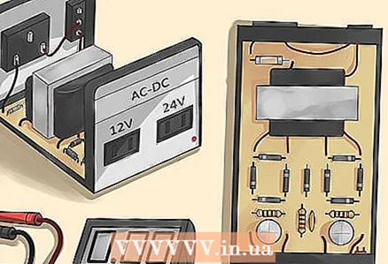 5 Get ready to measure the voltage on the networks. If necessary, remove covers and panels covering access to the network containing the transformer. For measurements, stock up with a digital multimeter (tester). You can buy this tester at an electrical or household goods store.
  6 Identify the transformer input. Connect the input circuit to the source. Using a tester in AC (alternating current) mode, measure the voltage across the primary winding. If it is more than 80 percent lower than expected, either the primary network or the transformer may be faulty. In this case, disconnect the primary winding from the input circuit. If after that the voltage at the input (but not on the disconnected primary winding) rises to the expected value, then the primary winding of the transformer is faulty. If the voltage does not rise, then the fault lies not in the transformer, but in the input circuit.
  7 Measure the voltage at the output of the transformer. If you determine that the output is not filtered or converted from the secondary, use the tester's AC mode. If there is filtering and signal conversion, switch the tester to DC mode. If the tester does not show the expected output voltage, either the transformer or the signal filtering and conversion unit is damaged. Check all the components of this block separately. If all of them are in order, then the transformer is faulty.
Tips
- A buzzing or crackling sound often indicates that the transformer is about to burn out.
- Do not assume that the primary and secondary windings of a transformer are grounded the same, often their grounding potentials are different. Consider this in your measurements.
Warnings
- During measurements, with circuits open and connected to the source, touching them is dangerous. Only touch the circuit elements with the test leads of the tester.
What do you need
- Circuit diagram
- Digital multimeter (tester)


