Author:
Carl Weaver
Date Of Creation:
26 February 2021
Update Date:
1 July 2024

Content
You can improve the quality of radio signal reception at FM frequencies (88MHz - 108MHz) at home, and with ease - for this you just need to replace the antenna with a 5/8 lambda dipole antenna. Many radios and most home receivers have an external antenna connector. Usually the supplied antenna is a simplified version (sometimes it is a built-in antenna or a telescopic pole, or just a small piece of wire). You can improve it significantly for very little money.Anything you need can be purchased at your nearest electronics store or hardware store.
Steps
 1 Determine the frequency of the station you want to tune in. The antenna is tuned to a specific wavelength depending on the frequency of the received radio signal. Regardless of the specific frequency, the entire FM broadcast band (88 - 108 MHz) of the radio receiver will receive a stronger signal from the antenna with the highest gain at the frequency selected at this stage, and slightly less gain at other frequencies.
  2 Calculate the length of the antenna. The formula for a 5/8 lambda antenna using a conventional "balanced cable" with a characteristic impedance of 300 ohms is as follows: L = 300 / f x 5/8 x 1/2; where "L" is the antenna length in meters and "f" is the frequency in MHz of the station being tuned. It can be simplified to the form L = 93.75 / f.
 - An antenna created for the mid-FM range of 88MHz - 108MHz (98MHz) should be 0.9566 meters or 95.66 cm (centimeters) long. For those who are more comfortable using the British imperial system of measures than the metric system, the formula for converting centimeters to inches is as follows: cm X 0.3937. This means the antenna must be 95.66 cm X 0.3937 = 37.66 inches long.
 3 Improve antenna design. The antenna enhancement discussed in this article is the creation of a simple 5/8 lambda antenna in the form of a "loop dipole" or "T" -shaped antenna. This design will be superior in performance to any built-in or telescopic antenna that may have been supplied with the receiver. It will also be similar to the antennas that come with some of the more expensive stereo receivers.
 - An improvement for such a simple design would be to use a double, triple (and so on) dipole with a corresponding length of 37.66 "x 2 = 75.32" (191.31 cm), 37.66 "x 3 = 112.98" (286.97 cm), etc.
- An antenna with a length of 112.98 "(286.97 cm) will outperform a 75.32" (191.31 cm) antenna, which in turn will outperform a 37.66 "(95.66 cm) antenna.
- Of course, there is a "point of no return" when the increase in size is so great that the signal from the ends of the antenna cannot travel the entire length due to the electrical resistance of the wire. This limit is approximately 100 meters (slightly longer than the length of a football field).
 4 Cut off the feeder part. As stated above, the antenna looks like a "T". All previous calculations were for the top horizontal part (top of the letter T) of the antenna. The vertical part (lower part of the T) should be connected to the horizontal part to facilitate the connection of the antenna to the receiver antenna connector. Although the horizontal and vertical portions function as an antenna, the vertical portion is called a feeder line.
 - Cut a piece of balanced cable equal to or multiple of the previously calculated length. This will be enough to create the horizontal portion of the antenna when you create it.
- 600 ohm and 450 ohm cables are physically larger than a balanced 300 ohm cable and are rated for 600 and 450 ohms, respectively, as opposed to 300 ohms for a balanced cable. These types of cables can also be used, but a different formula is required for the calculations. A standard balanced 300 ohm cable was chosen due to its wide availability.
 5 Prepare the antenna for connection to the feeder line. Find and mark the midpoint of the horizontal length of the antenna.
 - Use the razor blade to make a 1 inch (2.5 cm) notch (centered at the midpoint of the antenna length) that will run between the two wires in the balanced cable, parallel to them.
- Cut one of the wires at the midpoint of the antenna length.
- Strip the insulation from the cut ends of the wire at the midpoint of the antenna length and at the ends of the horizontal section (approximately 1/2 in. (1.27 cm) on each side).
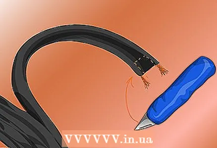 6 Prepare the feed line for connection to the antenna. Use a razor blade to cut about an inch (2.5 cm) between the wires of the balanced cable at both ends. Carefully strip half an inch (1.27 cm) of insulation from the wires at both ends of the cable.
  7 Tin the cable wires with solder. Twist the strands of the wires so that they are grouped. If soldering is not an option, proceed to the next step after stripping the wire insulation.
 - Apply a small amount of soldering flux (do not use water pipe soldering flux as it contains acid). A small 20 or 50 watt soldering iron or iron will be enough to heat the wire.
- Once the flux has melted, apply the solder to the wire near the tip of the soldering iron (using solder paste or flux-containing solder will work as well - but do not use acidic solders).
- Apply enough solder to the heated wire so that the molten solder reaches the insulation, then remove the solder and move the soldering iron away from the wire. Do this for both wires at (1) both ends of the feed line, (2) both wires at both ends of the horizontal portion of the antenna, and (3) both wires in the notch made in the center of the horizontal portion.
 8 Solder the antenna and feed line. Solder the two wires together at one end of the horizontal section and repeat the same for the other end (if soldering is not possible, create a strong electromechanical connection by twisting the ends of the wires tightly together).
 - Place the end of the feeder line in the center of the horizontal section of the antenna so that the tinned ends of the wires are close together. The left wire of the feeder line should be soldered to the left wire of the antenna and the right wire of the feeder line to the right wire of the antenna.
- If you did everything correctly, the signal path can be traced as follows: if you start with one wire of the feed line, it should go to one of the wires of the bottom of the antenna, go to one of the ends of the antenna. Next, he must go along the top wire of the antenna to its other end. Then it must return along the other bottom wire of the antenna to the second wire of the feeder line and get to the end of the feeder line.
Tips
- You will need a 300 to 75 ohm adapter if the receiver only allows connection to a 75 ohm antenna (coaxial cable). These are devices that accept a balanced 300 ohm cable, convert the signal and have a 75 ohm connector.
- The antenna assembled here is a "balanced" antenna and does not fit into a telescopic antenna that is "unbalanced". If your radio does not have an external antenna connector, you can simply attach a piece of any wire (the longer the better) to the existing antenna and lift the end up (the higher the better) towards the transmitter you want to receive the signal from.
Warnings
- Outdoor antennas must have lightning protection for the feeder line.
What do you need
- Balanced antenna cable 300 Ohm
- 20-50 watt soldering iron / iron
- Solder / Rosin (not water pipe solder)
- Flux (not water pipe flux)
- Adapter 300 Ohm - 75 Ohm (if necessary)
- Wire stripper
- Nippers
Similar articles
- How to connect a computer to a TV
- How to connect a laptop to a TV
- How to transfer an audio cassette to a computer
- How to check if the remote control is transmitting an infrared signal
- How to crimp a coaxial cable
- How to connect a home theater
- How to add a turntable to your stereo system


