Author:
Marcus Baldwin
Date Of Creation:
15 June 2021
Update Date:
24 June 2024
Content
- Steps
- Method 1 of 2: Labeling Large Capacitors
- Method 2 of 2: Interpreting Capacitor Labels
- Tips
- Warnings
- Similar articles
Capacitor labeling has a lot of variety compared to resistor labeling. It is difficult to see the markings on small capacitors because the surface area of their bodies is very small. This article explains how to read the markings of almost all types of modern capacitors manufactured abroad. Your capacitor may be labeled in a different order (compared to what is described in this article). What's more, some capacitors lack voltage and tolerance values - you only need a capacitance value to create a low voltage circuit.
Steps
Method 1 of 2: Labeling Large Capacitors
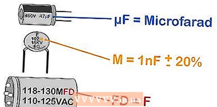
 1 Familiarize yourself with the units of measure. The basic unit of measure for capacitance is farad (F). One farad is a huge value for a conventional circuit, so household capacitors are labeled with sub-multiples.
 - 1 µF, uF, mF = 1 μF (microfarad) = 10 F. (Attention! In cases not related to the marking of capacitors, 1 mF = 1 mF (millifarad) = 10 F)
- 1 nF = 1 nF (nanofarad) = 10 F.
- 1 pF, mmF, uuF = 1 pF (picofarad) = 10 F.
 2 Determine the capacity value. In the case of large capacitors, the capacitance value is applied directly to the case. There may be some differences, of course, but in most cases look for a number in one of the units described above. You may need to consider the following points:
 - Ignore the uppercase letters.For example, the marking "MF" is mF, that is, microfarad (here the marking "MF" does not mean "megafarad", since capacitors with such a capacity do not exist).
- Pay attention to the "fd" markings. This is an abbreviation for the English word "farad" (farad). For example, the marking "mmfd" is mmf, that is, picofarad.
- Be careful with markings consisting of a number and only one letter, for example "475m". These markings are usually applied to small capacitors. In this case, skip to the next section of this article.
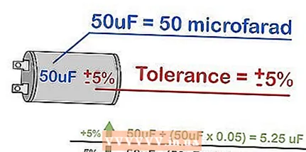 3 Determine the tolerance value. On the case of some capacitors, a tolerance value is applied, that is, the permissible deviation of the nominal capacitance from the specified one; consider this information if, when assembling an electrical circuit, it is necessary to know the exact value of the capacitance of the capacitor. For example, if the capacitor is marked "6000uF + 50% / - 70%", then its maximum capacity is 6000+ (6000 * 0.5) = 9000 μF, and the minimum is 6000- (6000 * 0.7) = 1800 μF.
 - If percentages are not listed, look for a letter located separately or after the numerical value of the capacitance. A specific letter denotes a specific tolerance value. To interpret such markings, go to step five of the next section.
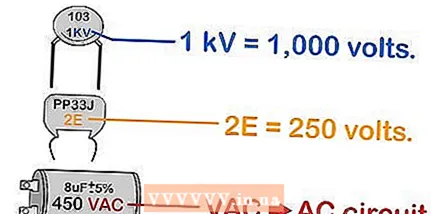 4 Determine the rated voltage. If the capacitor case is quite large, a numerical voltage value is stamped on it, followed by the letters V or VDC, or VDCW, or WV (from English Working Voltage - operating voltage). This is the maximum allowable capacitor voltage and is measured in volts (V).
 - 1 kV = 1000 V.
- If only one letter or one number and one letter is used to label voltage, go to step seven of the next section. If there is no voltage value on the capacitor case at all, use such a capacitor exclusively when assembling low-voltage circuits.
- If you are assembling an AC circuit, use a capacitor designed specifically for that circuit. Do not use a DC link capacitor unless you know how to convert the rated voltage and how to safely use such a DC link capacitor.
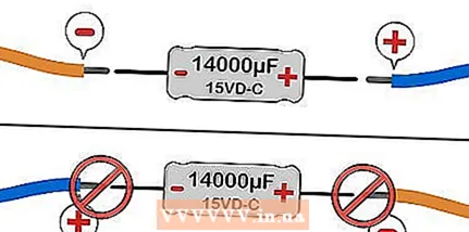 5 Look for the symbols "+" or "-". If one of these symbols is present on the case of a capacitor, such a capacitor is polarized. In this case, connect the positive ("+") contact of the capacitor to the positive terminal of the power supply; otherwise, the capacitor may short-circuit or the capacitor may explode. If there are no “+” or “-” symbols on the case, you can connect the capacitor in the circuit as you like.
 - To indicate polarity, some capacitors have a colored stripe or an annular indentation. This marking indicates a negative ("-") contact on aluminum electrolytic capacitors (the shape of such capacitors is similar to the shape of a tin can). On tantalum electrolytic capacitors (very small), this marking indicates a positive ("+") contact. Do not pay attention to the color coding if there are "+" or "-" symbols on the case, or if the capacitor in question is not electrolytic.
Method 2 of 2: Interpreting Capacitor Labels
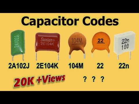
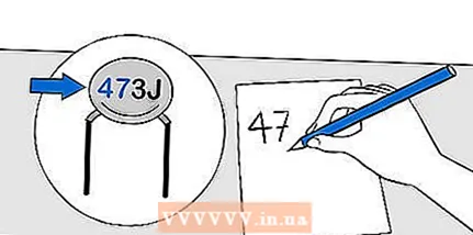 1 Write down the first two digits of the capacity value. If the capacitor is small and the capacitance value does not fit on its case, it is marked in accordance with the EIA standard (this is true for modern capacitors, which cannot be said about old capacitors). First, write down the first two digits, and then do the following:
 - If the marking consists of only two numbers and one letter, for example, 44M, then the first two numbers are the capacitance value of the capacitor. Skip to the third step of this section to find out how to determine the units of measure.
- If one of the first two characters is a letter, go to step four.
- If all three characters are numbers, go to the next step.
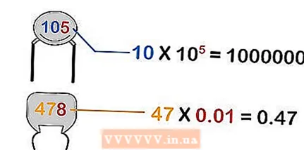 2 Use the third digit as a factor of zero. If the capacitance of the capacitor is marked with three numbers, then such a marking is interpreted as follows:
 - If the third digit is a digit from 0 to 6, add the corresponding number of zeros to the first two digits. For example, marking "453" is 45 x 10 = 45000.
- If the third digit is 8, multiply the first two digits by 0.01. For example, marking "278" is 27 x 0.01 = 0.27.
- If the third digit is 9, multiply the first two digits by 0.1. For example, marking "309" is 30 x 0.1 = 3.0.
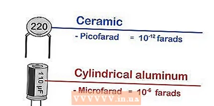 3 Define Units... In most cases, the capacitance of the smallest capacitors (ceramic, film, tantalum) is measured in picofarads (pF, pF), which are equal to 10 F. The capacitance of large capacitors (aluminum electrolytic or two-layer) is measured in microfarads (μF, uF or µF), which are equal 10 F.
 - It is possible that a letter indicating the unit of measurement will be affixed to the capacitor case, for example, p - picofarad, n - nanofarad, u - microfarad. But if there is one letter after the numbers, most likely this is the marking of the tolerance value, and not the marking of the unit of measure (as a rule, the letters "p" and "n" are not involved in the marking of the tolerance value, but there are exceptions).
 4 Interpret markings that include letters... If one of the first two characters of the label is a letter, interpret it as follows:
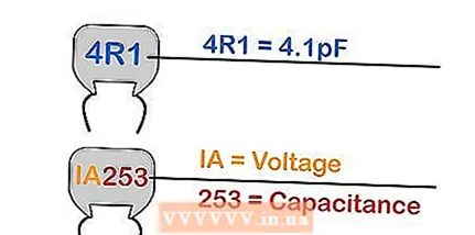
 - Replace the letter "R" with a decimal point and get the capacitance value measured in picofarads. For example, marking "4R1" is a capacitance of 4.1 pF.
- The letters "p", "n", "u" denote the unit of measurement (picofarad, nanofarad, microfarad, respectively). Replace these letters with a decimal point. For example, marking "N61" is a capacitance equal to 0.61 nF; similarly, "5u2" is 5.2 μF.
- For example, the marking “1A253” needs to be split into two parts. The “1A” marking indicates the voltage value, and the “253” marking indicates the capacitance value (read the information above).
- 5Determine the tolerance value of the ceramic capacitors. Ceramic capacitors are flat, circular and have two contacts. The tolerance value of such capacitors is given as one letter immediately after the three-digit capacitance marker. Tolerance is the permissible deviation of the nominal capacity from the indicated one. If you need to know the exact value of the capacitance, interpret the label as follows:

- B = ± 0.1 pF.
- C = ± 0.25 pF.
- D = ± 0.5 pF (for capacitors less than 10 pF) or ± 0.5% (for capacitors greater than 10 pF).
- F = ± 1 pF or ± 1% (similar to the letter "D").
- G = ± 2 pF or ± 2% (similar to the letter "D").
- J = ± 5%.
- K = ± 10%.
- M = ± 20%.
- Z = + 80% / -20% (If the required letter is not in the list, take into account the indicated capacitance of the capacitor.)
 6 Determine the value of the tolerance when the marking is "letter-number-letter". This marking is applied to many types of capacitors and is interpreted as follows:
 - The first symbol (letter) indicates the minimum temperature. Z = 10ºC, Y = -30ºC, X = -55ºC.
- The second character (number) indicates the maximum temperature. 2 = 45ºC, 4 = 65ºC, 5 = 85ºC, 6 = 105ºC, 7 = 125ºC.
- The third symbol (letter) indicates the change in the capacitance value within the specified temperatures, starting with the most accurate: BUT = ± 1.0%, and ending with the least accurate: V = 22,0%/-82%. R is one of the most common symbols: R = ± 15%.
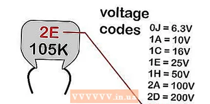 7 Determine the voltage value... A complete list of symbols is given in the table of the EIA standard, but in most cases the following symbols are used to indicate the maximum allowable voltage (values are shown only for capacitors designed for DC circuits):
 - 0J = 6.3V
- 1A = 10 V
- 1C = 16V
- 1E = 25 V
- 1H = 50 V
- 2A = 100 V
- 2D = 200 V
- 2E = 250 V
- If voltage is indicated by only one letter, this is an abbreviation of the markers above. If there is a number in front of the letter, for example, 1A or 2A, interpret this marking according to the situation.
- For the interpretation of less common characters, pay attention to the first number. 0 - less than 10 V; 1 - 10-99 V; 2 - 100-999 V and so on.
 8 Interpretation of other markings. Older capacitors or capacitors made for special needs may use different markings. This article does not cover other types of markings, but the following tips will tell you where to look for the information you need.
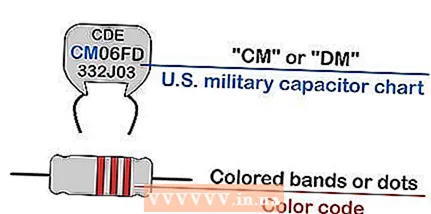
 - If a capacitor is labeled with a long string of characters starting with “CM” or “DM,” the capacitor is manufactured for the US Army.
- If the marking is a collection of colored stripes or dots, look for information on the color coding of the capacitors.
Tips
- By marking, you can determine the value of the operating voltage of the capacitor. The capacitor must be rated for a voltage greater than the voltage in your circuit; otherwise, you will encounter circuit malfunctions (possibly the capacitor will explode).
- 1,000,000 pF (picofarad) = 1 μF (microfarad). The capacitances of many capacitors are close (to a certain extent) to the indicated value, therefore the capacitance can be given both in picofarads and in microfarads. For example, if the capacitance is 10,000 pF, it will most likely be quoted as 0.01 μF.
- Yes, it will not be possible to determine the capacitance only by shape and size, but it can be roughly determined based on how the capacitor is used:
- The largest capacitors are found in television monitors and in power supplies. Each of them can have a capacitance from 400 to 1000 μF. If such a capacitor is improperly handled, it can be fatal.
- Large capacitors can be found in older radios and can range from 1 to 200 μF.
- Ceramic capacitors are usually smaller than a thumb; they are attached to the circuit with two pins. They are widely used and their capacitance ranges from 1 pF to 1 μF, and sometimes goes up to 100 μF.
Warnings
- Be careful when handling large capacitors as they can build up a life-threatening charge of electricity. Such capacitors are discharged using a suitable resistor. Do not short-circuit a large capacitor, otherwise it may explode.
Similar articles
- How to solder
- How to solder electronics
- How to use an ohmmeter
- How to discharge a capacitor
- How to check a capacitor
- How to read the color coding of resistors
- How to make a Tesla coil
- How to check a transistor
- How to create a parallel electrical circuit


