Author:
Ellen Moore
Date Of Creation:
17 January 2021
Update Date:
1 July 2024
Content
Potentiometers, also known as voltage dividers, are a type of electrical component called a variable resistor. They usually function in conjunction with a handle; the user turns the knob, and this rotational movement is converted into a change in the resistance of the electrical circuit. This change in resistance is then used to adjust some parameters of the electrical signal, such as the volume of the sound. Potentiometers are used in all types of consumer electronics, as well as larger mechanical and electrical equipment. Fortunately, if you have experience with electrical components, learning how to wire a potentiometer is fairly easy.
Steps
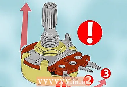 1 Locate the 3 terminals of the potentiometer. Position the potentiometer so that the adjusting knob is facing up and the 3 terminals are facing you. If the potentiometer is in this position, then the terminals from left to right can be conditionally numbered as 1, 2 and 3. Write this numbering on them, since when you change the position of the potentiometer in the course of further work, you can easily confuse them.
 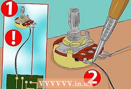 2 Ground the first terminal of the potentiometer. When used as a volume control (by far the most common application), terminal 1 provides ground. To do this, you need to solder one end of the wire to the terminal and the other end to the case or frame of the electrical component or device.
 - Start by measuring the length of the wire required to connect the terminal to the chassis at a convenient location. Use scissors to cut the wire to the desired length.
- Use a soldering iron to solder the first end of the wire to terminal 1. Solder the other end to the body of the component. This will ground the potentiometer, thereby providing zero voltage while the adjusting knob is at its minimum position.
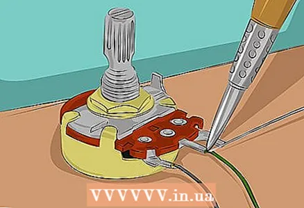 3 Connect the second terminal to the output of the circuit. Terminal 2 is the potentiometer input, i.e. the output line of the circuit must be connected to this terminal. For example, on an electric guitar, this should be the wire coming from the pickup. In the amplifier, this should be the lead from the preamplifier. Solder the wire to the terminal at the junction as described above.
 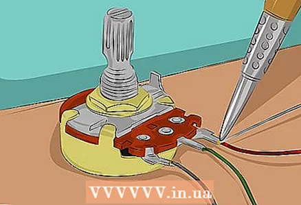 4 Connect the third terminal to the input of the circuit. Terminal 3 is the potentiometer output, i.e. it must be connected to the input of the circuit. On an electric guitar, this means connecting terminal 3 to the output jack. In an amplifier, this means connecting terminal 3 to the speaker terminals. Solder the wire carefully to the terminal.
 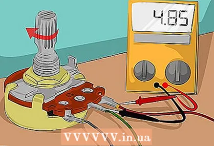 5 Test the potentiometer to make sure you connected it correctly. If you have connected a potentiometer, you can test it with a voltmeter. Connect the voltmeter leads to the input and output terminals of the potentiometer and turn the adjusting knob. When you turn the adjusting knob, the voltmeter reading should change.
 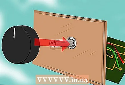 6 Place the potentiometer inside the electrical component (device). Once the potentiometer is connected and tested, you can place it however you like. Place the cover on the electrical component and, if necessary, place the knob on the working adjusting shaft of the potentiometer.
Tips
- These instructions describe how to connect a power adjustment potentiometer, which is the most common application. Other tasks can be performed using the potentiometer, which will require different wiring diagrams.
- For other uses using only 2 wires, such as electric motors, you can build a homemade dimmer by connecting one wire to the output and the other to the input.
Warnings
- Be sure to disconnect all electronic components before doing any work on them.
What do you need
- Potentiometer
- Wires
- Scissors
- Soldering iron
- Solder
- Voltmeter
- Pen


