Author:
Judy Howell
Date Of Creation:
5 July 2021
Update Date:
1 July 2024

Content
- To step
- Method 1 of 5: Using a digital multimeter with capacity setting
- Method 2 of 5: Using a digital multimeter without a capacity display
- Method 3 of 5: Using an analog multimeter
- Method 4 of 5: Testing a capacitor with a voltmeter
- Method 5 of 5: Short the capacitor contacts
- Tips
- Necessities
Capacitors are electronic components used in electronic circuits for storing voltage, such as those in the fans and compressors of heaters and air conditioning systems. Capacitors come in two main types: electrolytic (used in tube and transistor amplifiers) and non-electrolytic (used for controlling DC voltage pulses). Electrolytic capacitors can fail by discharging or because there is insufficient electrolyte and charge can no longer be retained. Non-electrolytic capacitors usually fail due to the leakage of stored charge. There are several ways to test a capacitor to see if it is still functioning properly.
To step
Method 1 of 5: Using a digital multimeter with capacity setting
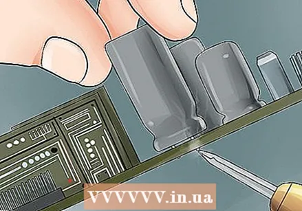
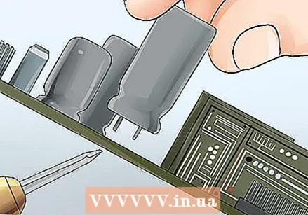
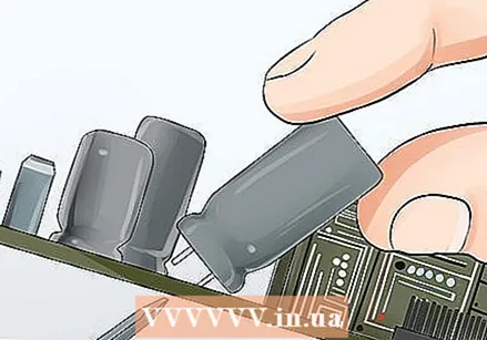
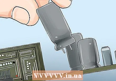
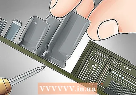 Disconnect the capacitor from the circuit it is part of.
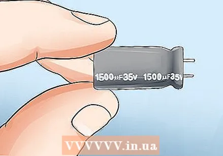 Read the value of the capacitance on the outside of the capacitor. The unit of electrical capacity is the farad, which is abbreviated with a capital "F". You may also see the Greek letter mu (µ), which looks like a lowercase "u" with a tail underneath. (Since the farad is a large unit, most capacitors measure capacitance in microfarad - a microfarad is one millionth of a farad.)
 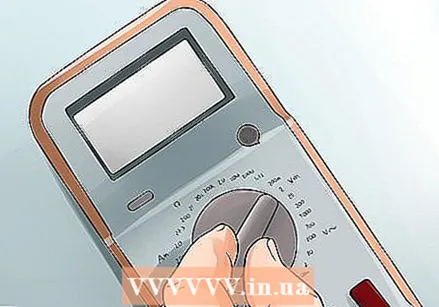 Set your multimeter to measure the capacitance.
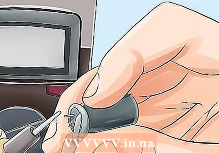 Connect the multimeter's probe tips to the capacitor. Plug the multimeter's positive (red) probe to the capacitor's anode and the negative (black) probe to the capacitor's cathode. On most capacitors, especially electrolytic capacitors, the anode wire is longer than the cathode wire.
  Check the reading provided by the multimeter. If the capacitance on the multimeter is close to the value printed on the capacitor itself, then the capacitor is good. If it is significantly less than the value printed on the capacitor (or zero), then the capacitor is broken.
Method 2 of 5: Using a digital multimeter without a capacity display
 Disconnect the capacitor from the circuit.
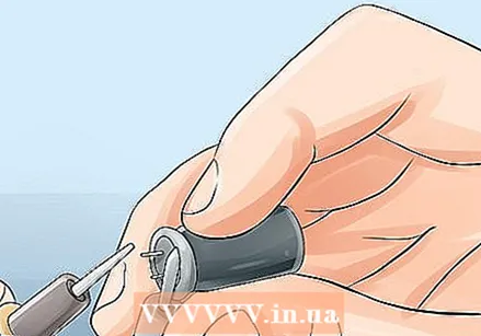
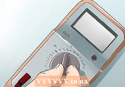 Set your multimeter to resistance. This setting can be marked with the word "OHM" (the unit for resistance) or the Greek letter omega (Ω) (the abbreviation for ohm).
 - If your measuring device has an adjustable resistor, then set the range to 1000 ohm = 1 K or higher.
 Connect the multimeter's probe tips to the capacitor wires. Again connect the red probe to the positive (longer) wire and the black probe to the negative (shorter) wire.
  Consider the value indicated by the multimeter. Write down the first resistance value, if desired. The value should quickly return to what it was before connecting the probes.
 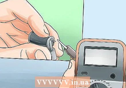 Repeat connecting and disconnecting the capacitor several times. You should always get the same result as with the first test. If you do this, the capacitor is still okay.
 - If the resistance value does not change in any of the tests, the capacitor is broken.
Method 3 of 5: Using an analog multimeter
 Disconnect the capacitor from its circuit.
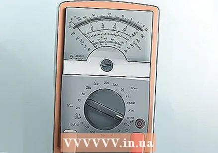 Set the multimeter to resistance. As with the digital multimeter, this may be labeled "OHM" or an omega (Ω).
 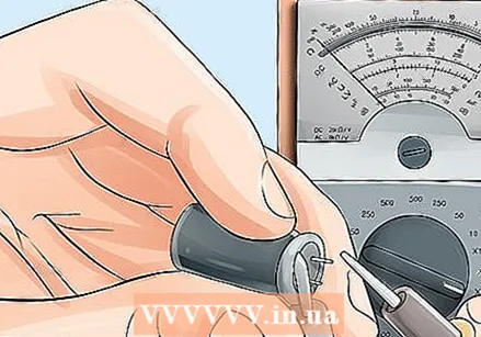 Connect the multimeter's probes to the capacitor contacts. Red on the positive (longer) wire, and black on the negative (shorter) wire.
 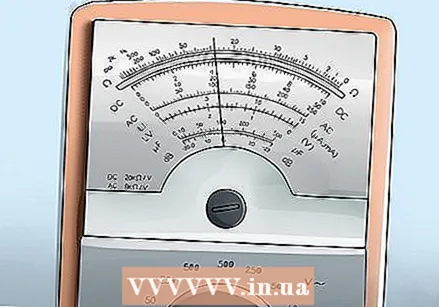 Check out the results. Analog multimeters use a pointer to display their results. How the pointer behaves determines whether the capacitor is still working.
 - If the needle initially shows a low resistance value and then gradually shifts to the right, the capacitor is still OK.
- If the needle shows a low resistance value and is not moving, the capacitor is shorted. You will have to replace it.
- If the needle is not showing a resistance value and is not moving or has a high value and is not moving, then the capacitor is an open (dead) capacitor.
Method 4 of 5: Testing a capacitor with a voltmeter
 Disconnect the capacitor from its circuit. You can disconnect only one of the two contacts from the circuit, if desired.
 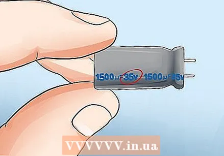 Check the voltage of the capacitor. This information should be printed on the outside of the capacitor. Find a number followed by a capital letter "V" (the symbol for "volt").
 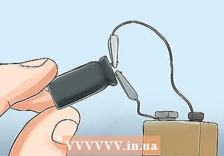 Charge the capacitor with a known voltage less than but close to the rated voltage. For a capacitor of 25 V you could use a voltage of 9 V, while for a capacitor of 600 V, you could use a voltage of at least 400 volts. Let the capacitor charge for a few seconds. Make sure that the positive (red) probe of the voltage source is connected to the positive (longer) contact of the capacitor, and the negative (black) probe to the negative (shorter) contact of the capacitor.
 - The greater the discrepancy between the voltage of the capacitor and the voltage with which you charge it, the longer it will take to charge. In general, the higher the voltage of the power source you can access, the higher the voltage rating of the capacitors that you can easily test.
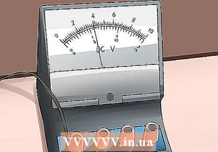 Set your voltmeter to DC voltage (if the device is suitable for reading both AC and DC).
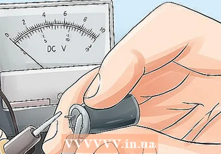 Connect the voltmeter's test probes to the capacitor contacts. Connect from the positive (red) probe to the positive (longer) lead and the negative (black) probe to the negative (shorter) lead of the capacitor.
 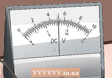 Note the voltage of the first measurement. This should be close to the voltage you fed the capacitor with. If not, the capacitor will no longer work properly.
 - The capacitor will discharge its voltage in the voltmeter, causing the reading to drop to zero if you leave the probes connected for a long time. This is normal. Only if the first reading is much lower than the expected tension should you start to worry.
Method 5 of 5: Short the capacitor contacts
 Disconnect the capacitor from its circuit.
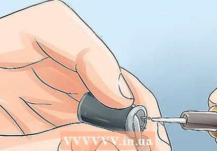 Attach test leads to the capacitor. Attach the positive (red) probe to the positive (longer) wire and the negative (black) probe to the negative lead of the capacitor.
 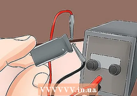 Connect the test probes shortly together. Do not short circuit them for longer than one to four seconds.
 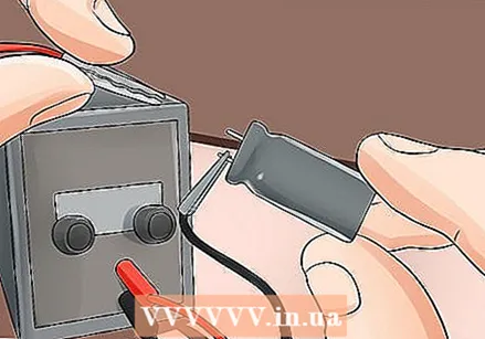 Disconnect the probe tips from the power supply. This is to prevent damage to the capacitor when you perform the task and to reduce the chance that you will receive an electric shock.
 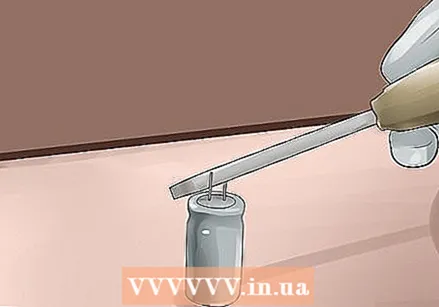 Short circuit the capacitor contacts. Make sure you wear insulating gloves and don't touch anything made of metal with your hands when doing this.
 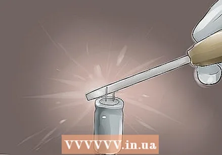 Look at the spark created when you short the test probe. The potential spark will give you an indication of the capacitor's capacity.
 - This method only works with capacitors that can hold enough energy to produce a spark while shorting.
- This method is not recommended because it can only be used to determine whether or not the capacitor has enough charge to produce a spark while shorting. It cannot be used to check if capacitor capacitance is within specifications.
- Do not use this method with larger capacitors, as this can cause serious injury or even death!
Tips
- Non-electrolytic capacitors are generally not polarized. When testing these capacitors, you can connect the probe of the voltmeter, multimeter or power supply to the wires of the capacitor.
- Non-electrolytic capacitors are divided into the types of materials they are made of - ceramic, mica, paper or plastic - with the plastic capacitors being further divided by the type of plastic.
- Capacitors used in heating and air conditioning systems are divided into two types. Run-on capacitors maintain a constant voltage on the fan motors and compressors in furnaces, air conditioners and heat pumps. Starting capacitors are used in units with higher torque motors in some heat pumps and air conditioners to provide the extra energy needed at start-up.
- Electrolytic capacitors usually have a 20% tolerance. It means that a capacitor that works properly can be 20% higher or 20% lower than its rated capacitance.
- Be careful not to touch the capacitor while it is charging, or you may receive a shock.
Necessities
- Analog or digital multimeter (or dedicated ohmmeter)
- Voltmeter
- Insulated gloves
- Power supply, preferably an adjustable power supply
- Metal tool for shorting capacitors (such as a screwdriver)
- Capacitor to be tested


