Author:
John Pratt
Date Of Creation:
17 April 2021
Update Date:
1 July 2024
Content
- To step
- Method 1 of 4: Series connection
- Method 2 of 4: Parallel connection
- Method 3 of 4: Combined circuit
- Method 4 of 4: Power formulas
- Tips
There are two ways to connect electrical components. Series circuits are components that are connected one after the other, while in a parallel circuit components are connected in parallel branches. The way resistors are coupled determines how they contribute to the total resistance of the circuit.
To step
Method 1 of 4: Series connection
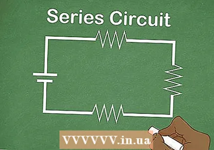 Learn to recognize a series connection. A series connection is a single loop, with no branches. All resistors or other components are arranged in sequence.
 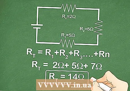 Add up all resistances. In a series circuit, the total resistance is equal to the sum of all resistances. The same current passes through each resistor, so each resistor behaves as expected.
 - For example, a series connection has a resistance of 2 Ω (ohms), 5 Ω, and 7 Ω. The total resistance of the circuit is 2 + 5 + 7 = 14 Ω.
 Instead, start with the amperage and voltage. If you don't know what the individual resistor values are, you can calculate them with Ohm's Law: V = IR or voltage = current x resistance. The first step is to determine the current in the circuit and the total voltage:
 - The current of a series circuit is the same at all points of the circuit. If you know what the current is at a particular point, you can use that value in the equation.
- The total voltage is equal to the voltage of the power supply (battery). It is not equal to the voltage across one component.
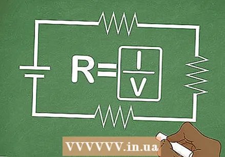
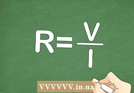
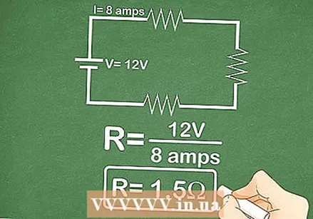 Use these values in Ohm's Law. Rearrange V = IR to solve for the resistance: R = V / I (resistance = voltage / current). Apply the values found to this formula to get the total resistance.
 - For example, a series circuit is powered by a 12 volt battery, and the current is equal to 8 amps. The total resistance across the circuit is then R.T. = 12 volts / 8 amps = 1.5 ohms.
Method 2 of 4: Parallel connection
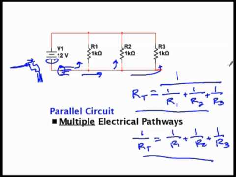
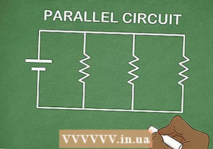 Understand parallel circuits. A parallel circuit branches off into several paths, which then come together again. Current flows through every branch of the circuit.
 - If the circuit has resistors on the main branch (before or after the branch) or if there are two or more resistors on one branch, continue with the instructions for a combined circuit.
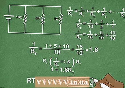 Calculate the total resistance of the resistor in each branch. Since each resistor only slows down the current passing through one branch, it has only a small effect on the total resistance of the circuit. The formula for the total resistance R.T. is
 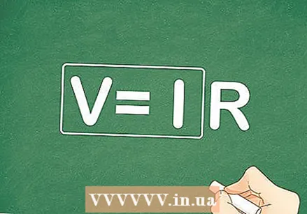 Instead, start with the total current and voltage. If you don't know the value of the individual resistors, then you need the value of the current and voltage:
 - In a parallel circuit, the voltage across one branch is equal to the total voltage across the circuit. As long as you know the voltage across one branch you can continue. The total voltage is also equal to the voltage of the circuit power source, such as a battery.
- In a parallel circuit, the current across each branch can be different. You have the total current, otherwise you cannot find out what the total resistance is.
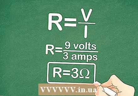 Use these values in Ohm's Law. If you know the total current and voltage across the entire circuit, you can find the total resistance using Ohm's Law: R = V / I.
 - For example, a parallel circuit has a voltage of 9 volts and a current of 3 amps. The total resistance R.T. = 9 volts / 3 amps = 3 Ω.
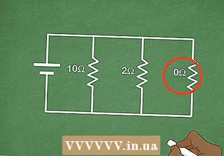 Pay attention to branches with zero resistance. If a branch of a parallel circuit has no resistance, all current will flow through that branch. The resistance of the circuit is then zero ohms.
 - In practical applications, this usually means that a resistor stops working or is bypassed (shorted) so that the higher current can damage other parts of the circuit.
Method 3 of 4: Combined circuit
 Divide your circuit into series and parallel connections. A combined circuit has a number of components that are connected in series (one behind the other), and other components that are connected in parallel (in different branches). Look for parts of your diagram that can be simplified into series or parallel connections. Circle each of these pieces to help you memorize them.
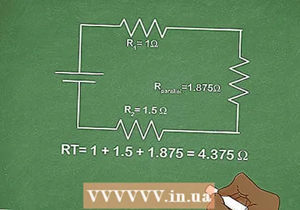
 - For example, a circuit has a resistance of 1 Ω and a resistance of 1.5 Ω connected in series. After the second resistor, the circuit splits into two parallel branches, one with a 5 Ω resistor and the other with a 3 Ω resistor.
Circle the two parallel branches to distinguish them from the rest of the circuit.
- For example, a circuit has a resistance of 1 Ω and a resistance of 1.5 Ω connected in series. After the second resistor, the circuit splits into two parallel branches, one with a 5 Ω resistor and the other with a 3 Ω resistor.
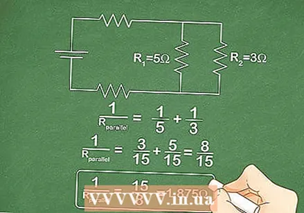 Look for the resistance of each parallel section. Use the parallel resistance formula
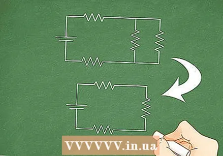
  Simplify your diagram. Once you have found the total resistance of a parallel section, you can cross out that entire section in your diagram. Treat that section as a single wire with a resistance equal to the value you found.
 - In the example above, you can ignore the two branches and consider them as one 1.875 Ω resistor.
 Add the series resistors together. Once you've replaced each parallel circuit with a single resistor, your diagram should be a single loop: a series circuit. The total resistance of a series circuit is equal to the sum of all individual resistances, so just add them together to get the answer.
 - The simplified diagram has a 1 Ω resistor, 1.5 Ω resistor, and the 1.875 Ω section you just calculated. These are all connected in series, so
 Use Ohm's Law to find the unknown values. If you don't know what the resistance is in a particular component of your circuit, look for a way to calculate it anyway. If you know what the voltage V and the current I is across that component, determine its resistance with Ohm's Law: R = V / I.
- The simplified diagram has a 1 Ω resistor, 1.5 Ω resistor, and the 1.875 Ω section you just calculated. These are all connected in series, so
Method 4 of 4: Power formulas
 Learn the formula for power. Power is the degree to which the circuit consumes energy and the extent to which it supplies energy to whatever drives the circuit (such as a lamp). The total power of a circuit is equal to the product of the total voltage and the total current. Or in the form of an equation: P = VI.
 - Remember, when you solve this for the total resistance, you need the total power of the circuit. It is not enough just to know the power that goes through one component.
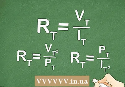
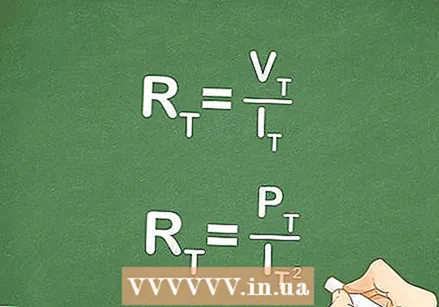 Determine the resistance using the power and current. If you know these values, you can combine the two formulas to find the resistance:
 - P = VI (power = voltage x current)
- Ohm's Law tells us that V = IR.
- Replace IR with V in the first formula: P = (IR) I = IR.
- Rearrange to determine resistance: R = P / I.
- In a series circuit, the current over one component is the same as the total current. This does not apply to a parallel connection.
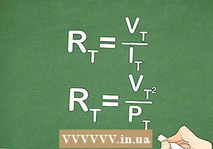 Determine the resistance using the power and voltage. If you only know the power and voltage, you can use the same approach to determine the resistance. Do not forget to use the full voltage across the circuit or the voltage of the battery that powers the circuit:
 - P = VI
- Rearrange Ohm's Law to I: I = V / R.
- Replace V / R with I in the power formula: P = V (V / R) = V / R.
- Rearrange the formula to solve for the resistance: R = V / P.
- In a parallel circuit, the voltage across a branch is the same as the total voltage. This is not true for a series connection: the voltage across one component is not equal to the total voltage.
Tips
- Power is measured in watts (W).
- Voltage is measured in volts (V).
- Current is measured in amperes (A) or in milliamps (mA). 1 ma =
A = 0.001 A.
- The power P as used in these formulas refers to the direct measure of the power at a specific moment in time. If the circuit uses alternating current (AC), the power is constantly changing. Electricians calculate the average power of AC circuits with the formula P.average = VIcosθ, where cosθ is the power factor of the circuit.


