Author:
Janice Evans
Date Of Creation:
25 July 2021
Update Date:
1 July 2024
Content
- Steps
- Method 1 of 3: Getting Started
- Method 2 of 3: Testing the Relay Coil
- Method 3 of 3: Testing the Solid State Relay
- What do you need
A relay is a separate device (as opposed to an integrated circuit) used to control high power signals with low power signals. The relay separates and protects the low voltage circuit from the high voltage circuit by means of an electromagnetic coil. This article will tell you how to test both a relay (solid state) and a coil.
Steps
Method 1 of 3: Getting Started
 1 Find the relay diagram or specifications. In most cases, the relay has a standard pinout, but it is still best to check the relay diagram (if any) to check the configuration and number of pins. As a rule, such information is applied to the relay housing.
 - To test the relay, you will need the values of its voltage and current, the location of the contacts and other information. Such data can be found in the corresponding documentation (reference technical sheets), which will allow you to avoid errors when testing the relay. Of course, it is possible to test a relay without knowing the configuration of its contacts, but if the relay is damaged, the test results can be unpredictable.
- In some cases, the technical parameters of the relay are applied to its case (this is more likely, the larger the relay is).
 2 Examine the relay. Many relays have a transparent plastic case, inside of which the contacts and coil are clearly visible. If you notice visible damage (for example, traces of melting or black deposits), then the relay is defective.
 - Most modern relays have a built-in LED that signals the normal operation of the relay. If the LED is off and the relay or coil is energized, then the relay is damaged.
 3 Disconnect the relay from the power supply. Before working on any electrical device, disconnect it from any power source, such as an electrical outlet or battery.Pay special attention to capacitors, which build up electrical charges and can store them for extended periods of time (even after disconnecting from the power source). Do not short-circuit the contacts of the capacitor in order to discharge it.
 - Check local regulations before using electrical appliances and leave it to a professional unless you can guarantee that the necessary precautions are being taken. This advice does not apply to low voltage devices, but basic precautions should be followed.
Method 2 of 3: Testing the Relay Coil
 1 Determine the specifications of the relay coil. Find its number (so-called part number) on the relay housing. Determine the voltage and amperage of the control coil in the appropriate documentation for the part number. Also, this data can be found on the case of large relays.
  2 Determine if the driving coil is diode protected. The diode serves to protect the logic circuit from impulse noise. In the circuit diagram, a diode is indicated by a triangle with a short line in contact with one of the vertices of the triangle. This line indicates the input (positive contact) of the control coil.
  3 Find the relay pin configuration. It can be found in the relevant documentation or on the case of a large relay. A relay can have one or more poles, which are indicated in the diagram as a switch connected to a relay contact.
 - Each pole can have a normally open (NO) and a normally closed (NC) contact. In the diagram, such contacts are indicated as connections with relay contacts.
- In the diagram, each pole either touches a contact, which indicates a normally closed contact (NC), or does not touch a contact, which indicates a normally open contact (NO).
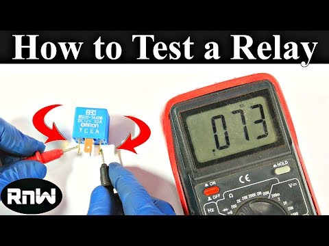
 4 Disconnect the relay from the power supply and check the relay contacts. Using a digital multimeter, determine the resistance between each pole of the relay and the corresponding normally closed (NC) and normally open (NO) contacts. There is no resistance between the pole and the normally closed contact (that is, it is equal to 0), but between the pole and the normally open contact, the resistance will be infinitely large.
  5 Connect the relay to a power source. Select a battery as a source, the parameters of which correspond to the technical characteristics of the relay coil. If the relay coil is protected by a diode, consider the polarity of the power supply when connecting it to the relay. When the relay is energized, you will hear a click.
  6 Check relay contacts energized. Using a digital multimeter, determine the resistance between each pole of the relay and the corresponding normally closed (NC) and normally open (NO) contacts. The resistance between the pole and the normally closed contact will be infinitely large, but there will be no resistance at all between the pole and the normally open contact (that is, it is equal to 0).
Method 3 of 3: Testing the Solid State Relay
 1 Use an ohmmeter to test the solid state relay. In most cases, when the solid state relay closes, it will fail. An ohmmeter is used to test normally open relay contacts in the absence of a control voltage.
 - Open the relay case, switch the normally open contact, and then close the relay case (0.2 is the internal resistance of the ohmmeter when the test voltage is present).
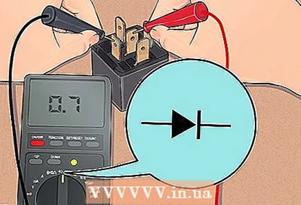 2 Use a multimeter in diode test mode to confirm your findings. If you determine that the relay is faulty, confirm this fact; To do this, take a multimeter, switch it to diode test mode and check A1 (+) and A2 (-). The multimeter will apply a small test voltage to the relay to activate the semiconductor and check the voltage between the gate and source of the transistor.
 - If the relay is damaged, the multimeter will display "0".If the relay is working properly, the multimeter will show "0.7" (in the case of a silicon transistor) or "0.5" (in the case of a germanium transistor, which is very rare).
 3 Don't let the relay overheat. A solid state relay is easy to repair and will last much longer if not allowed to overheat. Typically, modern relays have a DIN rail compatible housing.
 - There are also SCR relays, which are designed to control the temperature in heating cables and infrared lamps and ovens. These relays have an increased switching speed and are often damaged by sudden temperature changes.
What do you need
- Voltage source
- Digital multimeter


