Author:
Marcus Baldwin
Date Of Creation:
18 June 2021
Update Date:
16 September 2024

Content
- Steps
- Part 1 of 4: Reading the Basics
- Part 2 of 4: Reading Architectural Sheets
- Part 3 of 4: Reading the rest of the plans
- Part 4 of 4: Gaining Advanced Knowledge of Architectural Drawings
- Tips
- Warnings
- What do you need
The first requirement in constructing a building according to a project is an understanding of architectural drawings, which are also called blueprints or blueprints. If you want to know how to read these drawings and understand exactly what they say, then just follow these steps.
Steps
Part 1 of 4: Reading the Basics
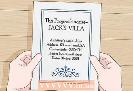 1 Reading the title page. The title bar contains the project name, architect's name, address, contact information, project location and date. This page is very similar to the cover of a book. Some title pages also indicate the final drawing of the building, after completion of construction and landscaping.
 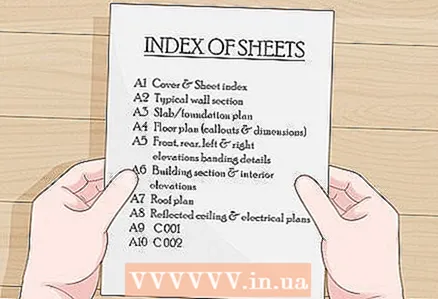 2 Reading the plan directory. These pages indicate the page numbers of the plan, and sometimes their content. The decoding of abbreviations, the scale bar with which the plan must be correlated and, sometimes, notes on finishing are also indicated.
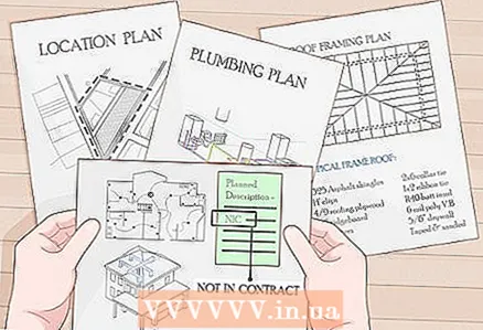
 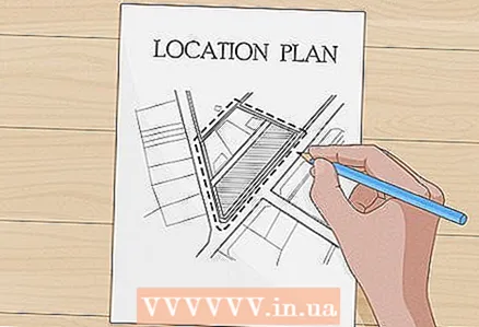 3 Reading the layout plan. There will be a map of the area with an enlarged map of the location of the construction, which will provide information on the location of the project in relation to nearby cities and highways. This sheet is not present in all plans.
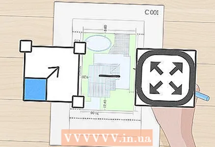
 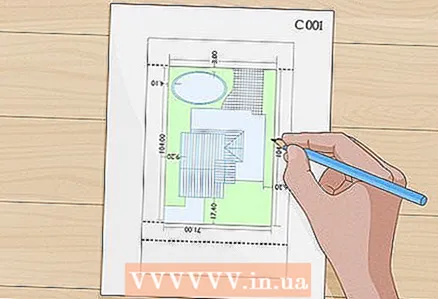 4 Reading the project of the planning of the territory. The numbering of these pages usually contains the letter "C", for example, pages C001, C002, and so on. The site planning project usually contains the following information:
 - Topographic information. It will provide builders with information on topography, slopes and flatness of the area.
- Demolition plan. This page (or pages) will show the buildings or landmarks to be demolished in order to locate the building. Objects that will not be demolished, such as trees, will be indicated in the notes.
- Communication plans of the area. These sheets indicate the location of existing underground utilities in order to preserve them during earthworks and construction.
Part 2 of 4: Reading Architectural Sheets
 1 Be aware you don't have to scale the drawing. If you cannot make sense of the dimensioned drawing, get more dimensions from the architect.
 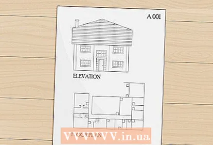 2 Understanding architectural sheets. These pages are usually numbered using the letter A, for example A001, A002 or A1-X, A2-X, A3-X, and so on. They will describe and describe the measurements of floor plans, geodetic heights, building bodies, wall sections, and other parts of the building's design and construction. These sheets are broken down into many parts, thus forming a building plan that you need to understand. The parts you will need to know are described below.
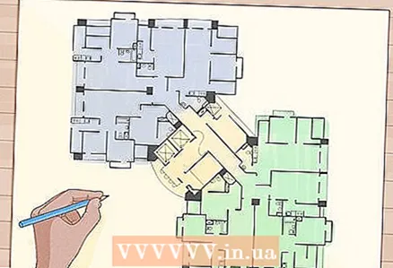
 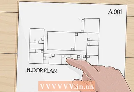 3 Reading floor plans. These sheets will show the location of the building walls and identify components such as doors, windows, bathrooms, and other elements. The dimensions will be indicated as the distance between or from the center to the center of the walls, the width of the door and window openings and changes in the heights of the floor if it is multi-level.
 - Floor plans are composed of different levels of detail, depending on the stage of the project. In stage D (layout), drawings can only show the basic elements of the space.
- During the demonstration stage, the drawings will be more detailed in the image of all the elements of the space on a larger scale in order to give the contractor an estimate of the material part of the work.
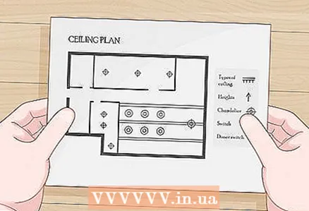 4 Reading leveled plans. Here the architect indicates the types, heights and other elements of the ceilings at various locations in the building. This plan may not be included in individual projects.
  5 Reading a roofing plan. These pages will show the location of beams, rafters, trusses, crossbars and other roofing elements, as well as formwork and deck details.
 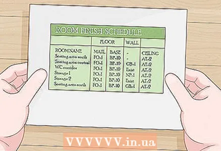 6 Reading the finishing work plan. This is usually a table that lists the finishing materials for each room. The list should include: paint color for each wall, floor finishing materials, ceiling heights, appearance, color, wall base and other notes / details for finishing work.
 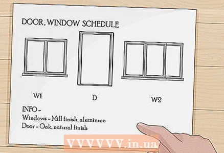 7 Reading a sheet of filling window / door openings. A list of doors is entered into this table, describing the opening, door handles, information about windows (usually transferred from the floor plan, for example, a window / door of type "A", "B", and so on). This list may also include details for installing waterproof elements, fastening methods, and material specifications. For windows and doors, separate statements are sometimes compiled (although not in all projects). For windows - "Aluminum, rental", and for doors - "Oak, natural finish".
 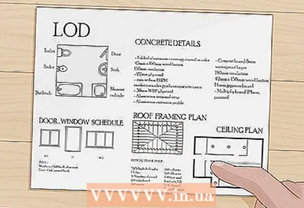 8 Reading the rest of the elements. These may include the location of the lighting fixtures in the bathroom, the cabinets that make up the cabinets, and other items not usually listed on the remaining sheets. Such as (not necessarily these) concrete information, details of doors and windows, roofing and water repellent elements, elements of walls, doors, wall formwork and other details. Each project is unique and may not / include what is in other projects. The level of detail is determined by the architects for each individual project. The designation of more details is gaining popularity, since it will be easier for the contractor to understand what to include and how much it will cost, and he will not have to guess himself about the details of the building. Some contractors may not / may have comments on the level of detail, but this has nothing to do with what the licensed architect deems it necessary to explain when demonstrating the project.
 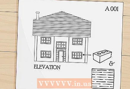 9 Reading the facade plan. These are images of the house from the outside with an indication of the material used for the external walls (brick, plaster, vinyl, and so on), the location of windows and doors, roof slopes and other elements of the exterior of the building.
Part 3 of 4: Reading the rest of the plans
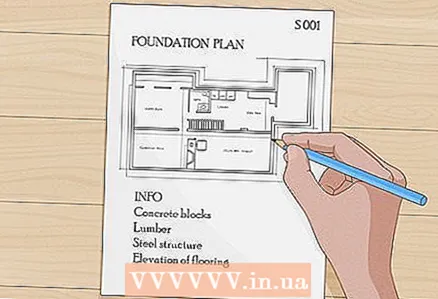 1 Reading structural plans. Structural plans are usually numbered using the letter "S", for example S001. These plans indicate reinforcement, foundations, slab thicknesses, and framing materials (lumber, concrete pilasters, structural steel, concrete blocks, and so on). Below are the different aspects of the outline plans that you need to be able to read:
 - Foundation plan. These sheets will show the size and thickness of the supports with notes on rebar placement. Anchor bolts or weld plates for structural steel and other elements will be indicated.
- The support placement plan is most often shown on the first page of the structural plan notes, along with notes regarding reinforcement requirements, concrete strength, and other written structural strength and test requirements.
- Floor plan. The materials used for the flooring of the building will be indicated here. Metal or timber beams, concrete masonry or structural steel.
- Intermediate structural floor plans. They are present in the plans of multi-storey buildings, where each floor may require supporting columns, beams, beams, formwork and other elements.
- Foundation plan. These sheets will show the size and thickness of the supports with notes on rebar placement. Anchor bolts or weld plates for structural steel and other elements will be indicated.
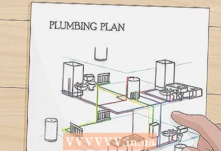 2 Reading the section of water supply and sewerage. Numbering with the letter "P". These sheets will show the position and view of the sewerage system located in the building. Note: Often these plans are not included in home design materials. Below are the parts of the water and sanitation plan that you should read:
 - Rough sewer plan.Shows the location of pipes that will be installed and connected to plumbing to obtain plumbing, sewerage and ventilation systems. Rarely found in individual plans (separate family home plan).
- Floor plan for water supply and sewerage. Shows the location and type of plumbing, the route of pipes (on the ceiling or in the walls) for drinking water, drains and ventilation. These plans are attached by most architects (for cottages), indicating the location of the plumbing on the floor plan.
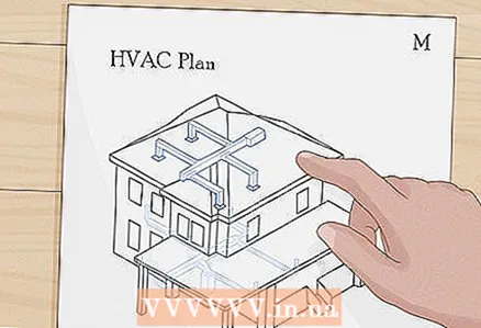 3 Reading mechanical drawings. Numbering with the letter "M". Shows the location of heating, ventilation and air conditioning equipment, air ducts and cooling sewers, electrical wiring. Rarely present in cottage plans.
 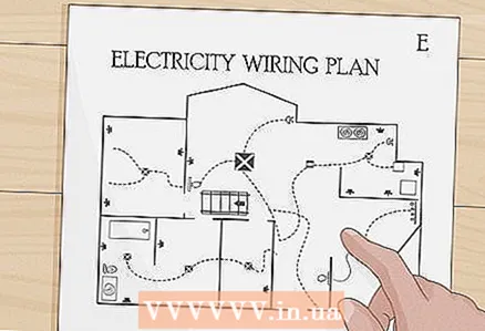 4 Reading the plan of electrical equipment and power supply. Numbering with the letter "E". Shows the location of electrical circuits, distribution boards and lighting, switchgear, accessory panels and transformers if included in the building.
 - Special pages found in the electrical and power plan can show wiring configuration, panel lists, current and fault limits, notes on wire types and sizes, and channel sizes.
- Some information cannot / can be included in the cottage plans.
 5 Reading the section on environmental planning. Shows protected areas, erosion control plans, and methods to prevent pollution during construction. The plan may include tree protection methods, fence installation requirements and temporary rainwater drainage methods.
 - Requirements for environmental planning are established by local, regional or state environmental authorities. This may not be required, depending on the building supervision regulations for the construction of cottages.
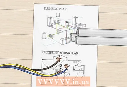 6 Remember that drawings for water supply and sewerage, electrical equipment and power supply, mechanical drawings are diagrams. Spatial drawings are rare and the location of communications according to the drawing, building rules and regulations falls on the shoulders of the builders. Make sure the drain is routed to suit the location of the plumbing. The same applies to wiring.
Part 4 of 4: Gaining Advanced Knowledge of Architectural Drawings
 1 Learn to position the first floor of a building according to an architectural blueprint. To do this, you will need to position the structural element you are considering to ensure that some of the work is done. When locating a building on the ground, you need to look at the plan to determine the surrounding buildings, structures, property boundaries in order to find the starting point for measuring the place on which the foundation will be laid. On some plans, they simply indicate the coordinates and you only need to take geodetic measurements to determine the desired point. Below is what you need to locate the building from the plans:
 - Indicate the location according to the algorithm described above or measurements given on the terrain plan. Mark the points, preferably corners, on one side of the future building and check the positioning accuracy using the poles. If you can not 100% accurately establish the line of the building, then you can assume its correctness and continue. This is a common practice when building over large areas, but if construction is carried out in densely built-up areas, then this approach is unacceptable.
- Determine the height at which you will start working. It can be taken relative to a nearby road or sea level. The site plan or architectural drawing of the first floor must have a reference point (the reference point refers to some landmark, such as a manhole or survey elevation with a known height) or a point with an elevation relative to an existing elevation as the starting point.
- Refer to the plan to calculate the position of each corner of the building for the offset. Memorize each element you use to locate the building. You can mark the outer wall line, foundation line or column line, depending on the type of structure and the most convenient element from which to start measuring.
- For example, if you are building a structural steel building with I-beams, which requires anchor bolts to secure them, then you can start positioning the building using the column centers. If you are building a wood vein building with a solid slab floor, then the slab edges are the ideal choice for measurements.
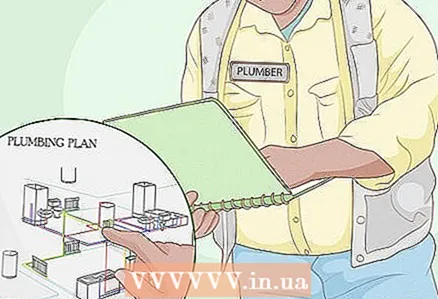 2 Refer to the descriptions of the various sheets in order to find the building element that you will use in your work. Plumbers use a floor plan to locate the walls, so the pipes they connect are positioned in the wall cavities while the building is being built, and then, using their water and sewage floor plan, determine the type and size of pipes required to connect to certain plumbing fixtures.
 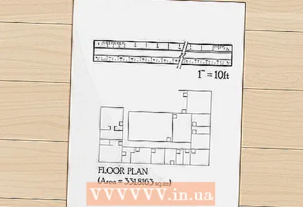 3 Use scaled measurement when measurements are not provided. Typically, architectural plans are drawn to scale. For example, 1 cm = 3m. So, when measuring the distance between the walls on the plan, there is a distance of 3 meters per 1 centimeter. The scale will make it easier to work, but be careful when correlating the scale on the plan. Architects often use a fractional scale (1/32), engineers usually use centimeter to meter. Some plans or details are not drawn to scale and should be marked (NPM).
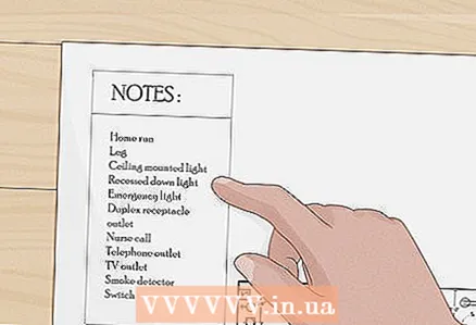
 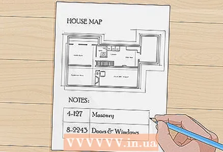 4 Read all the notes on the pages. Often, one particular element has special conditions that are easier to describe in writing than to represent graphically, and notes will be the architect's means of depicting this element. At the edge of the drawing sheet, you can see a table with notes with numbers that determine the position of the note on the plan (a number inscribed in a circle, square or triangle).
 - Sometimes one or more sheets with numbered notes to the drawing are added to the plan, which combines all or most of the notes from the whole project. Many architects organize all of their design notes into a building BOM list, using one to sixteen, or sometimes even more, divisions that categorize the notes.
- For example, the note “4-127” might refer to masonry, since section 4 represents stone work. Note 8-2243 may refer to door or window components because Section 8 talks about windows and doors.
 5 Learn to recognize the different lines that architects and engineers can use. You should also have a special table of key marks with you, giving information on abbreviations, symbols and special lines used in each part of the plan.
 - An example would be electrical and utility plans, which might indicate the cable from the first junction box to the switchboard, in highlight or ink darker than those that indicate other circuits. Open cable ducts are highlighted with a bold line, and hidden ones - with a dashed or dashed line.
- Due to the large number of lines used to denote different types of walls, pipes, wiring and other elements, you should have separate explanations for each page with you.
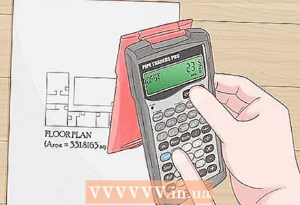 6 Use a building calculator to add measurements when determining plan distances. These are calculators for feet, inches, fractions, and metric measurements. Often architects do not measure specific parts of the plan marked “outside the building line”, so you need to be able to add the distances of each element with the specified measurements to calculate the exact length.
 - An example would be calculating the center of a bathroom wall to position and connect a pipe.You can add the distance from the object “outside the building” to the living room wall, then the distance to the corridor wall, then through the bedroom to the bathroom wall. It will look like: (11'5 '') + (5'2 ") + (12'4") = 28'11 ".
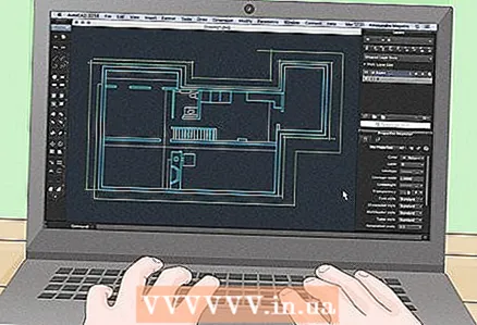 7 Use computer-assisted plans. If you have a complete set of drawings in electronic form, on a CD for example, then you will need a licensed version of the program that is designed to open such files. AutoCAD is a popular but very expensive professional design program and a designer can add a Viewer to the disc, which you can install on your computer to view the files. This way you will be able to view the drawing, but without the complete program, which prevents you from making adjustments to the drawing. Be that as it may, many architectural firms know how to protect their files, which are usually emailed to you for you to review (without adjustment, of course, since architects are responsible for the integrity of their work).
 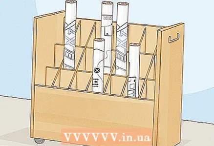 8 Learn to manage architectural plans. These collections of documents are usually in sheets of about 61x91cm, and a complete floor plan can include tens or hundreds of pages. They are either sewn or stapled along the left edge, they come off the attachment, tear if handled carelessly, ink discolors in direct sunlight, and rain makes them almost unusable.
 - It can cost thousands of dollars to restore these documents, so keep them safe and have a flat, wide work surface on which to unfold the plan and read the blueprints from it.
 9 Read the specs. Specifications are usually printed and stored in a folder. They contain descriptions of the methods and materials used in the project, as well as the verification methods, quality control information, geotechnical information, and other useful information for working on the project. However, some architects include specifications for the drawing sheets (in order to make sure that the sheets are not confused).
 - BOMs are the architect's way of specifying quality standards, materials, model numbers, and other design characteristics. Even cottage plans often have their own specifications. Specifications are usually divided into numbered sections, usually sections 1-16, but the number of sections has increased over the past ten years.
- Many architects numbered their paragraphs, with which they can cross the verbosity of specifications with drawings. This improves control over various purchases.
 10 Look for notes and symbols that refer to “detail by alt. price ”,“ selective improvements by the owner ”and“ add. ”. They may indicate parts of the work that are required by the architectural drawing but not required to be built, supplied or installed under the building contract. "NPC" - Not Under Contract, which means that a certain item or part will be installed in this place by the owner after the end of the project.
 - A “PSAP” or “PSMP” (Owner Provided, Contractor Installed, and Government Provided, Contractor Installed) indicates that the part was supplied by the customer but installed by the contractor. Read and understand the abbreviations used in your plan.
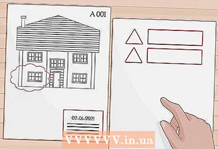 11 Revision. The architect can include "add.", That is, changes made to the document after they were posted on the bid. Many architects leave an empty section, usually in the lower right corner of the sheet, just above the number, leaving it under the revision list. Revisions are most often indicated by numbers enclosed in a triangle, circle, or other symbol. The date will be indicated to the right of each revision number, and to the right is a short description of the revision. Then, the revision number will appear on the drawing itself, in the area in which the changes were made. Often a "revision cloud" is added to the number in the form of a cartoon cloud around the revised segment. This will help everyone understand where the changes were made.Also, the architect usually sends an email summarizing the revisions contained in each supplement directly to the owner and registered clerk. Later - to various clerks to confirm the change of information for their suppliers of contracts and suppliers of materials.
Tips
- Be careful with drawing assemblies as they are "original size", while many plans are supplied in half and full size. With "full" dimensions, you will be able to calculate distances without the need to translate the scale.
- If the drawings are half size, then you will have to divide the measurements from the ruler by 2. Note: Many half-size drawings do not have this mark. Usually, half dimensions are considered drawings on a sheet less than 61x45cm. Remember, sometimes even those that have been transferred from a 76x112 cm sheet to a 28x43 sheet are called half-size drawings, which obviously will not be half.
- Check out home planning books or articles on the internet to get an idea of lines, measurements, and the simplest types of plans.
- Use the triangular ruler to scale the plan distances. The shape of these rulers allows them to adhere more tightly to the paper, which reduces the likelihood of error.
- When building an architectural plan, keep the blueprints in plain sight to document the changes with a red pencil or pen. This is called a red underline. After completing the work, the underlined sheets are sent to the draft. These drawings are called recorded drawings. Red lines indicate lines other than the initial ones indicated in the plan.
Warnings
- Be sure to collect all required permits before starting construction work. Stroynadzor can stop work on any project for which a permit is needed, which is absent after the start of construction. Fines are also issued.
- If in doubt about the measurements in the plan or their description, then consult with the architect who created the drawing instead of taking risks and making mistakes that will be difficult to correct later.
- Be aware that mechanical plans, plans for electrical equipment and power supply, water supply and sewerage do not always allow each communication to be given an individual location, so special attention should be paid to coordinating the installation of each component of the communication without conflict.
What do you need
- Plan table
- Architectural triangular scale bar
- Engineering triangular scale ruler
- Building calculator


