Author:
Tamara Smith
Date Of Creation:
25 January 2021
Update Date:
1 July 2024
Content
- To step
- Part 1 of 4: Familiarizing yourself with an analog multimeter
- Part 2 of 4: Measuring resistance
- Part 3 of 4: Measuring the voltage
- Part 4 of 4: Measure amps
- Tips
- Warnings
- Necessities
A multimeter is an instrument used to check for AC or DC voltages, resistance and continuity of electrical components, and small amounts of current in circuits. With this device you can check whether voltage is present on a circuit. In doing this, a multimeter can help you do a variety of useful tasks, such as measuring ohms, volts, and amps.
To step
Part 1 of 4: Familiarizing yourself with an analog multimeter
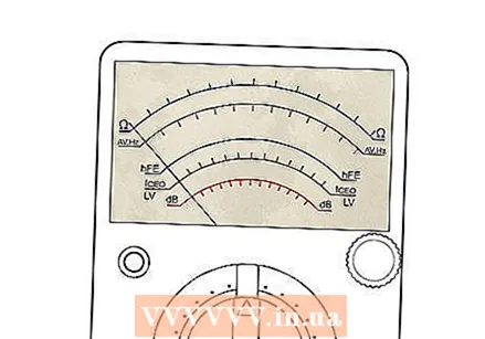 Look for the dial on an analog multimeter. It has arc-shaped scales and a pointer that indicates the values of the scale.
 - The arc-shaped markers on the meter dial may have different colors indicating each scale, so they will have different values. These determine the range of the result.
- A wider mirror-shaped surface in the shape of the shells can also be provided. The mirror is used to reduce what is called "parallax viewing error" by aligning the pointer with its reflection before reading the value indicated by the pointer. In the image it appears as a wide gray strip between the red and black measuring scales.
- Nowadays multimeters often have a digital readout, instead of the analog scale. The function is basically the same, only with a numerical result.
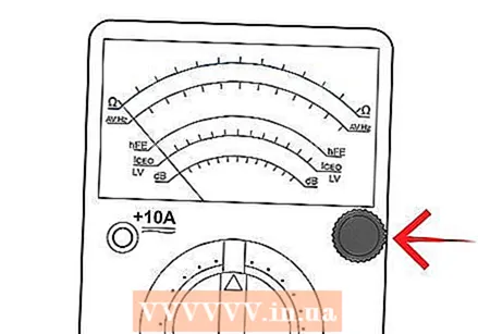
 Find the selector switch or button. This allows you to switch between volts, ohms and amps and change the scale (x1, x10, etc.) of the meter. Many functions have multiple ranges, so it is important to set both correctly, otherwise serious damage to the meter or injury to the user may occur.
 - Some meters have an "Off" position on this selector switch, while others have a separate switch to turn the meter off. The meter should be "Off" when it is stored and not in use.
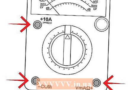 Find the inputs that the probes will be connected to. Most multimeters have several connections that are used for this purpose.
 - One is usually called "COM" or (-), which stands for "common". The black test lead is connected here. This is used for almost any measurement that is taken.
- The other input (s) should be labeled "V" (+) and the Omega symbol (an inverted horseshoe) for Volts and Ohms, respectively.
- The + and symbols represent the polarity of the probe tips when setting and testing DC voltage. If the test leads are installed as suggested, the red wire would be positive compared to the black test lead. This is nice to know when the circuit under test is not labeled + or -, as is usually the case.
- Many meters have additional connections that are necessary for current or high voltage testing. It is just as important to connect the test leads to the correct terminals as it is to set the selector switch range and test type (volts, amps, ohms). Everything must be correct. Consult the manual of the meter if you are unsure which connections to use.
 Find the probes. There must be two test leads or probes. Generally, one is black and the other is red. These are used to connect to whatever device you plan to test and measure.
 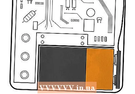 Find the battery and fuse. These are usually located on the back, but sometimes also on the side. Here you will find the fuse (and possibly a spare battery) and the battery that powers the meter for resistance testing.
 - The meter can have more than one battery and they can be of different sizes. A fuse is provided to help protect the meter movement. There is also often more than one fuse. A good fuse is necessary for the meter to function, and resistance / continuity testing requires fully charged batteries.
 Locate the zero button. This is a small button usually located near the dial and labeled "Ohms Adjust", "0 Adj" or similar. This is only used in the ohmic or resistance range, while the probe tips are shorted (touching each other).
 - Turn the knob slowly to move the needle as close to 0 position on the Ohm scale as possible. If new batteries are installed this should be easy to do, but a needle that does not go to zero indicates that batteries may need to be replaced.
Part 2 of 4: Measuring resistance
 Set the multimeter to Ohm or Resistance. Turn on the meter if it has a separate on / off button. When the multimeter measures resistance in ohms, it cannot measure continuity because resistance and continuity are opposite. If there is little resistance, there will be a lot of continuity and vice versa. With this in mind, you can make assumptions about continuity based on the measured resistance values.
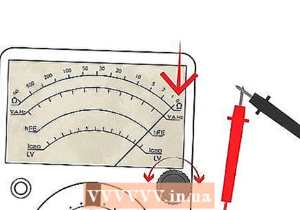
 - Find the Ohm scale on the dial. It is usually the top scale and has values that are highest to the left of the dial ("∞", an "8" on its side, for infinity), gradually decreasing to 0 on the right. This is opposite to the other scales, which have the lowest values on the left and increase to the right.
 Observe the meter reading. If the test leads are not in contact with anything, the needle or pointer of an analog meter will rest at the leftmost position. This represents an infinite amount of resistance, or an "open circuit". It's safe to say there is no continuity or path between the black and red probe tips.
  Connect the test leads. Connect the black test lead to the connector labeled "Common" or "-". Then connect the red test lead to the connector labeled Omega (Ohm symbol) or the letter "R" nearby.
 - Sets the range (if any) to R x 100.
 Hold the probe tips together at the ends of the test leads. The meter pointer should move all the way to the right. Locate the zero adjustment knob and turn it so that the meter reads "0" (or is as close to "0" as possible).
 - This position is the "short circuit" or "zero ohm" indication for the range R x 1 of this meter.
- Do not forget to reset the meter to "zero" immediately after changing the resistance ranges, otherwise you will get an erroneous reading.
- If you are unable to get a "zero ohm" indication, it could mean that the batteries are weak and need to be replaced. Try resetting as described above again, but with new batteries.
 Measure the resistance of something like a light bulb that you know is intact. Locate the lamp's two electrical contacts. These are the screw face and the center of the bottom of the base.
 - A possible assistant may only hold the lamp by the glass.
- Press the black probe against the threaded base and the red probe against the center point on the bottom of the base.
- Watch how the needle quickly moves from the rest point left to the right, to 0.
 Try different ranges. Change the range of the meter to R x 1. Reset the meter for this range and repeat the step above. Note that the meter did not go as far to the right as before. The resistor scale has been changed so that each number on the R scale can be read directly.
 - In the previous step, each number represented a value that was 100 times greater. For example, 150 was previously 15,000. Now 150 is only 150. If the scale R x 10 had been chosen, 150 would have been 1500. The scale chosen is very important for accurate measurements.
- Now that we know this, let's study the R scale. It is not linear like the other scales. Values on the left are more difficult to read accurately than those on the right. Trying to read 5 ohms on the meter while in the R x 100 range looks like 0. On the R x 1 scale it would be much easier to read this. Therefore, when testing the resistance, you should set the range so that the center can be read instead of the extreme left or right sides.
 Test the resistance between your hands. Set the meter to the highest possible R x value and set the meter to zero.
 - Hold a measuring pen in each hand and read the meter. Pinch both probes firmly. Note that the resistance has decreased.
- Release the probes and wet your hands. Hold the probes again. Note that the resistance has also decreased.
 Make sure your measurement is accurate. It is very important that the probes do not touch anything other than the device under test. A device that has burned out will not show "open" on the meter when tested if your fingers indicate an alternate path around the device, such as when touching the probes.
 - Testing round "cartridge fuses" and older automotive glass fuses will indicate low resistance if the fuse is on a metal surface when tested. The meter reads the resistance of the metal surface on which the fuse is located (providing an alternate path between the red and black probe tips around the fuse) rather than determining the resistance through the fuse. Any fuse in this case, good or bad, will indicate "good", giving you an erroneous analysis.
Part 3 of 4: Measuring the voltage
 Set the meter for the highest range provided for AC Volts. Often the voltage to be measured has an unknown value. For this reason, the highest possible range is selected so that the circuit and the movement of the meter are not damaged by a greater voltage than expected.
 - If the meter was set to the 50 volt range and tested a common Dutch outlet, the 220 volt from the outlet could damage the meter beyond repair. Start high and work your way down to the lowest range that can be safely displayed.
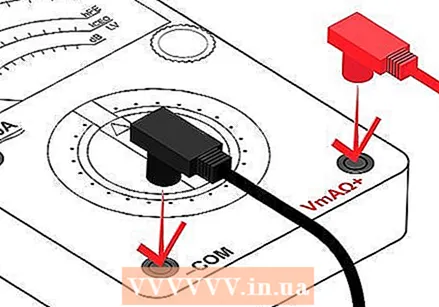 Place the probes. Plug the connector of the black probe into the "COM" or "-" input. Then insert the red probe into the "V" or "+" input.
  Find the voltage scales. There can be different voltage scales with different maximum values. The range selected with the selector determines which voltage scale to read.
 - The maximum value scale must coincide with the range of the selector switch. The voltage scales, unlike the Ohm scales, are linear. The scale is accurate throughout its length. Of course, it will be much easier to accurately read 24 volts on a 50 volt scale than on a 250 volt scale, where it may appear to be anywhere from 20 to 30 volts.
 Test a regular electrical outlet. In Europe you can expect a voltage of 220-240 volts. In other places such as in the US, a voltage of 120 is common, but 240 also occurs, while elsewhere you can also encounter 380 volts.
 - Push the black probe into one of the contact holes. It should be possible to let go of the black probe, as the contacts behind the front of the socket slightly clamp the probe, just like inserting a plug.
- Insert the red probe into the other input. The meter should indicate a voltage very close to 220 or 240 volts (depending on the type of outlet tested).
 Remove the probes. Rotate the mode dial to the lowest possible range that is greater than the specified voltage (220 or 240).
 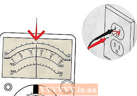 Place the probes as before. The meter can indicate between 220 and even 240 volts this time. The range of the meter is important for obtaining accurate readings.
 - If the pointer has not moved, it is likely that DC was chosen instead of AC. The AC and DC modes are not compatible. The right mode must be set. If not set correctly, the user would mistakenly believe that no voltage was present, which could be a dangerous error.
- Make sure you both modes when the pointer is not moving. Set the meter to AC volts and try again.
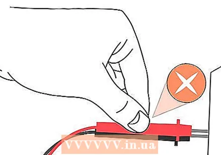 Do not try to hold both probes. If possible, try to connect at least one probe in such a way that it is not necessary to hold both while taking the tests. Some gauges have accessories with alligator clips or other types of clips that help do this. Minimizing your contact with electrical circuits drastically reduces the risk of burns or injuries.
Part 4 of 4: Measure amps
 Make sure you've measured the voltage first. You need to determine whether or not the circuit is AC or DC by measuring the voltage of the circuit as described in the previous steps.
  Set the meter to the highest supported AC or DC range for amps. If the circuit under test is AC, but the meter is only measuring DC amps (or vice versa), stop. The meter must be able to measure the same mode (AC or DC) of amperage as the voltage in the circuit, otherwise it will read 0.
 - Note that most multimeters will only measure extremely small amounts of current, in the uA and mA range. 1 uA is 0.000001 A and 1 mA is 0.001 A. These are values of the amperage that only flow in the most delicate electronic circuits, and are literally thousands (even millions) grinding smaller than the values seen in the home and auto circuitry that most homeowners would be interested in when it comes to testing them.
- As an example only: a typical 100W / 120V incandescent lamp requires 0.833 Amps. This amperage would likely irreparably damage the multimeter.
 If necessary, use an ammeter to be clamped. Ideal for the home owner, this meter can be used to measure amperage through a 4700 ohm resistor across 9 Volts DC.
 - To do this, insert the black probe into the "COM" or "-" connection and insert the red probe into the "A" connection.
- Make sure that no more current is flowing through the circuit.
- Open the part of the circuit to be tested (one or the other leg of the resistor). Insert the meter series with the circuit so that it completes the circuit. An ammeter is placed in series with the circuit to measure the current. It cannot be placed "over" the circuit like a voltmeter is used (otherwise the meter will likely be damaged).
- Observe the polarity. Current flows from the positive to the negative side. Set the current range to the highest value.
- Make sure that there is power across the circuit and adjust the range of the meter down to allow an accurate reading of the pointer. Do not exceed the range of the meter or it may be damaged. Readings of approximately two milliamps should be stated because according to Ohm's law I = V / R = (9 volts) / (4700 Ω) = 0.00191 A = 1.91 mA.
 Be on the lookout for any filter capacitors or other elements that require an inrush current (peak current) when turned on. Even if the operating current is low and within the range of the meter fuse, the peak current can be many times higher than the operating current because the empty filter capacitors almost behave like a short circuit. Blowing of the meter fuse is almost certain if the inrush current of the DUT (device under test) is many times higher than the value of the fuses. In any case, always use the higher range measurement, protected by the higher fuse, and be careful.
Tips
- If the multimeter stops working, you will need to run some tests, such as checking the fuse. You can get these at electronics stores.
- Make sure your multimeter is set to the correct setting for the device you are measuring or you will not get the correct results or no results at all.
- If you are going to check any part for continuity, you must turn off the power. Ohm meters provide their own power via an internal battery. Leaving the current on while testing the resistance will damage the meter.
Warnings
- Respect electricity. If you don't know something, ask questions and ask someone more experienced.
- Close never Connect a multimeter to a battery or voltage source if the meter is set to measure current (amperes). This is a common way of inflating a meter.
- Check always the meter on known good voltage sources to verify operational status before use. A faulty meter that tests for volts will read 0 volts regardless of the voltage present.
Necessities
- Multimeter. Consider a digital meter instead of the older analog types. Digital gauges usually offer an automatic range and easy-to-read display. Because they are electronic, the built-in software helps prevent damage from incorrect connection and provides better range than the mechanical meter movement on analog meters.


