Author:
Monica Porter
Date Of Creation:
18 March 2021
Update Date:
1 July 2024

Content
Wind is a stream of air moving in an almost horizontal direction from high pressure to low pressure. Strong winds can cause great damage as it puts pressure on the surface of a structure. The intensity of this pressure is called the wind load. The influence of wind depends on the size and shape of the structure. Wind load is a necessary parameter to be able to design, build buildings with better safety and wind resistance, and to install objects on the roof of the building such as antennas.
Steps
Method 1 of 3: Calculate the wind load using the general formula
Determine the generalized formula. The formula for calculating wind load is F = A x P x Cd, Inside F is wind force or wind load, A is the projected area, P is the wind pressure, and CD is the drag coefficient. This equation is useful for estimating the wind load on a given object, but does not meet the requirements in building standards for the design of a new building.
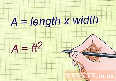
Find the projected area A. This is the area of the two-dimensional surface that the wind is blowing. For a more accurate analysis, you must repeat the calculation for each side of the building. For example, if the west side of the building is 20m, replace that value A to calculate the wind load on the west side.- The formula for area depends on the shape of the surface. For flat walls, use the formula Area = length x height. Approximate the column surface area with the formula Area = diameter x height.
- In the SI system, you need to measure A in square meter (m).
- In imperial measurements, you need to measure A in square feet (ft).
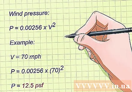
Calculate the wind pressure. The simple formula for calculating the imperial P-weighted wind pressure (pounds / square feet) is, in there V is the wind speed in miles per hour (mph). To find wind pressure in the SI system (Newton / square meter), you use, and measure velocity V in meters per second.- This formula is derived from the American Association of Civil Engineers standard set. The factor 0.00256 is the result of a calculation based on typical values of air density and gravitational acceleration.
- Engineers use a more precise formula to consider factors like surrounding terrain and building type. You can find the calculation formula in the ASCE 7-05 standard set, or use the UBC formula below.
- If you do not know what the wind speed is, check the highest wind speed in the area according to the standards of the Electronic Business Association (EIA). For example, most of the United States is in Zone A with wind speeds of 38.7 m / s, but the coastal areas are in Zone B (44.7 m / s) or Zone C (50 m / s).
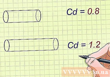
Determine the resistance coefficient of the object under consideration. The drag force is the force of the wind acting on the building, governed by the building shape, the surface roughness, and many other factors. Engineers often measure resistance directly through experiments, but if you want to estimate you can look up the typical drag coefficient for object geometry. For example:- The standard drag coefficient for long cylinders is 1.2 and for short cylinders is 0.8. These factors apply to the base of the antenna holding the antenna on many buildings.
- The standard drag coefficient for flat panels such as building faces is 2.0 for long flat sheets, or 1.4 for short flat panels.
- The drag coefficient has no units.
Calculate the wind load. Using the values found above, you can now calculate the wind load using an equation F = A x P x Cd.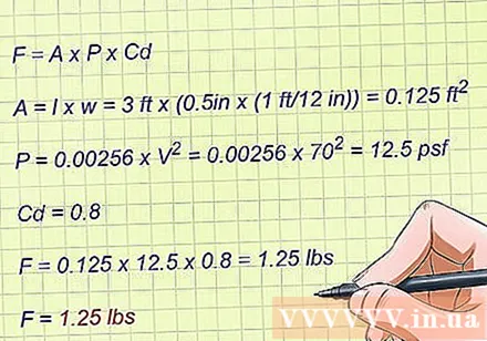
- Suppose you want to calculate the wind load acting on an antenna that is 1 meter in length and 2 cm in diameter, and has a wind speed of 31.3 m / s.
- Start by estimating the projected area. In this case,
- Calculate the wind pressure:.
- For short cylinders, the drag coefficient is 0.8.
- Instead of the equation:
- 9,6 N is the wind load acting on the antenna.
Method 2 of 3: Calculate the wind load using the formula of the Electronic Business Association
Identify the formula developed by the Electronic Business Association. The formula for calculating wind load is F = A x P x Cd x Kz x Gh, Inside A projection area, P is wind pressure, CD is the drag coefficient, Kz is the exposure coefficient, and GH is the coefficient of wind recoil. This wind load formula considers several additional parameters, and is often used to calculate the wind load acting on the antenna.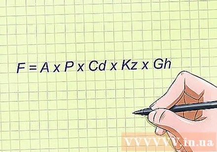
Understand the variables in formulas. To use this formula effectively, you must first understand the meaning of each variable and its unit.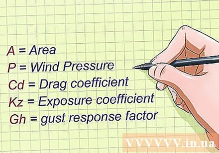
- A, P and CD has the same meaning as in the generalized formula.
- Kz is the coefficient of exposure and is calculated from the height from the ground to the midpoint of the object. The unit of Kz is the meter.
- GH is the recoil coefficient and is calculated by the total height of the object. The unit of GH is 1 / m or m.
Determine the projected area. The projected area of an object depends on its shape and size. If the wind is blowing on a flat wall, the projected area is easier than a circular object. The projected area will be approximately equal to the area that the wind is exposed. There is no formula for calculating the area of the view, but you can estimate it with some basic calculations. The unit of area is m.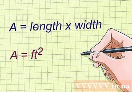
- For flat walls, use the formula Area = length x width, and measure the length and width of the wall where the wind is blown.
- For cylinders or columns, you can approximate the area by length and width. In this case, the width is the diameter of the cylinder or column.
Calculate the wind pressure. The wind pressure is calculated according to the formula P = 0.613 x V, Inside V is the wind speed in meters per second (m / s). The unit of wind pressure is Newton per square meter (N / m).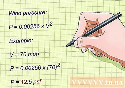
- For example, if the wind speed is 31.3 m / s then the wind pressure is 0.613 x 31.3 = 600 N / m.
- Another way to calculate the wind pressure at a particular velocity is to use wind velocity standards in different geographic areas. For example, according to the Electronic Business Association (EIA), most of the United States in Region A has wind speeds of 38.7 m / s, but coastal areas are in Zone B (44.7 m / s). ) or Zone C (50 m / s).
Determine the resistance coefficient of the object under consideration. The drag force is the force of the wind acting in the direction of blowing the object. The drag coefficient represents the resistance of an object in the fluid, and depends on the shape, size, and roughness of the object.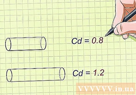
- The standard drag coefficient for long cylinders is 1.2 and for short cylinders is 0.8, which is commonly applied to antenna posts on many buildings.
- The standard drag coefficient for flat panels such as building faces is 2.0 for long flat sheets, or 1.4 for short flat panels.
- The difference between the resistance coefficient of the flat plate and the cylinder is approximately 0.6.
- The drag coefficient has no units.
Calculate the exposure coefficient Kz.Kz is calculated by the formula in which z is the height from the ground to the midpoint of the object.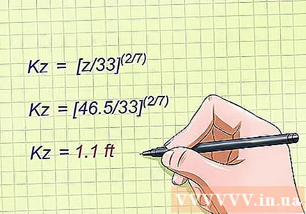
- For example, if you have an antenna that is 1 meter long and 15 meters from the ground, z will be 14.5 m.
- Kz = = = 0.8 m.
Calculate the coefficient of wind recoil GH. Wind recoil coefficient is calculated by the formula Gh = 0.65 + 0.6 /, Inside H is the height of the object.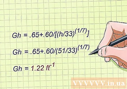
- For example, if you have an antenna that is 1 meter long and 15 meters from the ground, Gh = 0.65 + 0.6 / = 0.65 + 0.6 / = 1.32 m
Calculate the wind load. Using the values found above, you can now calculate the wind load using an equation F = A x P x Cd x Kz x Gh. Plug the values into the variables and perform calculations.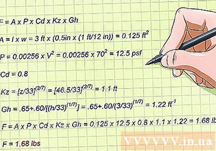
- Suppose you want to calculate the wind load acting on an antenna 1 meter long and 2 cm in diameter, 31.3 m / s wind speed. The antenna is located on top of a 15m high building.
- Start by calculating the projected area. In this case, A = l x w = 1 m x 0.02 m = 0.02 m.
- Calculate wind pressure: P = 0.613 x V = 0.613 x 31.3 = 600 N / m.
- For short cylinders, the drag coefficient is 0.8.
- Calculate the exposure coefficient: Kz = = = 0.8 m.
- Calculate the wind recoil coefficient: Gh = 0.65 + 0.60 / = 0.65 + 0.60 / = 1.32 m
- Instead of the equation: F = A x P x Cd x Kz x Gh = 0.02 x 600 x 0.8 x 0.8 x 1.32 = 10 N.
- 10 N is the wind load acting on the antenna.
Method 3 of 3: Calculate the wind load by the formula of the standard set UBC-97 (Uniform Building Code)
Determine the formula of UBC-97. This formula was built in 1997 in the UBC (Uniform Building Code) standard for calculating wind load. The formula is F = A x P, Inside A is the projected area and P wind pressure; but this formula has another way of calculating wind pressure.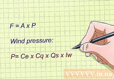
- Wind pressure (N / m) is calculated by the formula P = Ce x Cq x Qs x Iw, Inside Ce is the combined factor of the height, exposure and recoil of the wind, Cq is the pressure coefficient (equivalent to the drag coefficient in the two equations above), Qs is the stagnant pressure of the wind, and lw is the important factor. All these values can be calculated or looked up from the corresponding tables.
Determine the projected area. The projected area of an object depends on its shape and size. If the wind is blowing on a flat wall, the projected area is easier than a circular object. The projected area will be approximately equal to the area that the wind is exposed. There is no formula for calculating the area of the view, but you can estimate it with some basic calculations. The unit of area is m.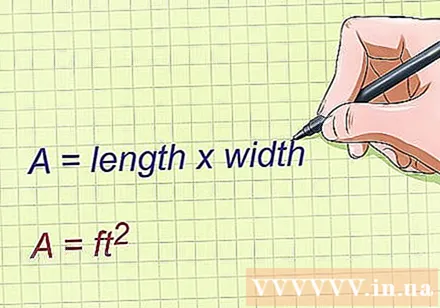
- For flat walls, use the formula Area = length x width, and measure the length and width of the wall where the wind is blown.
- For cylinders or columns, you can approximate the area by length and width. In this case, the width is the diameter of the cylinder or column.
Determined Ce, combined coefficient of height, exposure and wind recoil. This value is looked up from Table 16-G in UBC and considers three types of contact related to the terrain, with heights and values. Ce different for each model.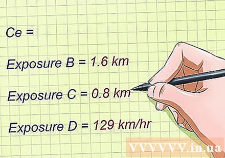
- "Type of exposure B is a terrain with houses, trees or other unevenness, covering at least 20% of the surrounding area and stretching from 1.6 km or more from the location under consideration."
- “The contact type C is flat and generally well ventilated, stretching 0.8 km or more from the site of consideration.”
- "D-exposure type is the terrain most severely affected, has an average wind speed of 129 km / h or higher, and flat terrain type without obstructions, surrounded by large waters."
Determine the pressure coefficient of the object under consideration. Pressure coefficient Cq is similar to the drag coefficient CD. The drag force is the force of the wind acting in the direction of blowing the object. The drag coefficient represents the resistance of an object in the fluid, and depends on the shape, size, and roughness of the object.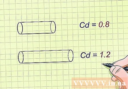
- The standard drag coefficient for long cylinders is 1.2 and for short cylinders is 0.8, which is commonly applied to antenna posts on many buildings.
- The standard drag coefficient for flat panels such as building faces is 2.0 for long flat sheets, or 1.4 for short flat panels.
- The difference between the resistance coefficient of the flat plate and the cylinder is approximately 0.6.
- The drag coefficient has no units.
Determine the stagnant pressure of the wind.Qs is the stagnant wind pressure and is calculated similarly to the wind pressure calculation in the previous equations: Qs = 0.613 x V, Inside V is the wind speed in meters per second (m / s).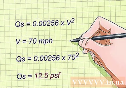
- For example, if the wind speed is 31 m / s, the stagnant wind pressure is 0.613 x V = 0.613 x 31.3 = 600 N / m.
- Another way is to use wind speed standards in different geographic areas. For example, according to the Electronic Business Association (EIA), most of the United States in Region A has wind speeds of 38.7 m / s, but coastal areas are in Zone B (44.7 m / s). ) or Zone C (50 m / s).
Determine the key factor.lw is an important coefficient and can be looked up from the 16-K table in the UBC. It is a multiplier factor used to calculate the load to consider the factors that use the building. If a building contains hazardous material, the critical factor will be higher than a building for general use.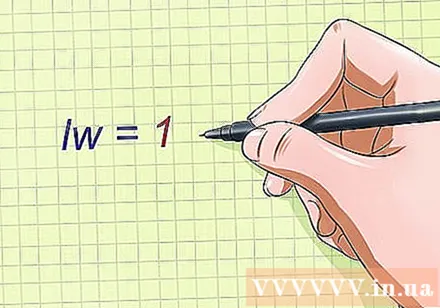
- Calculations for a building with a standard use will have a factor of 1.
Calculate the wind load. Using the values found above, you can now calculate the wind load using an equation F = A x P = A x Ce x Cq x Qs x Iw . Plug the values into the variables and perform calculations.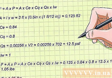
- Suppose you want to calculate the wind load acting on an antenna 1 meter long and 2 cm in diameter, 31 m / s wind speed. The antenna is placed on the top of a 15 m high building in an area with the terrain of Contact Type B.
- Start by calculating the projected area. In this case, A = l x w = 1 m x 0.02 m = 0.02 m.
- Determined Ce. According to Table 16-G, using a height of 15 m and topography of contact type B, we can look up Ce is 0.84.
- For short cylinders, the drag coefficient is good Cq is 0.8.
- Calculate Qs: Qs = 0.613 x V = 0.613 x 31.3 = 600 N / m.
- Determine the key factor. This is a standard building should lw = 1.
- Instead of the equation: F = A x P = A x Ce x Cq x Qs x Iw = 0.02 x 0.84 x 0.8 x 600 x 1 = 8 N.
- 8 N is the wind load acting on the antenna.
Advice
- You should know that the wind speed changes at different altitudes from the ground. Wind speed increases with height of the structure and closer to the ground, the more erratic change, because it is affected by structures on the ground.
- Remember it is this erratic variation that will reduce the accuracy of the wind load calculations.


